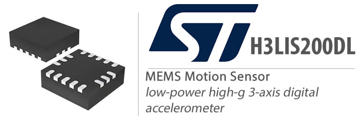
H3LIS200DL is a MEMS (Micro Electro Mechanical System) motion sensor manufactured by STMicroelectronics. It is designed to measure linear acceleration in three dimensions (X, Y, and Z axes) and can detect acceleration changes as small as 1mg (milli-g, where 1g is the acceleration due to gravity).
The H3LIS200DL is a low-power, high-performance sensor that can operate in a wide range of environments. It has a full-scale range of ±2g, ±4g, or ±8g, and can communicate with a host microcontroller using a digital I2C or SPI interface.

This sensor is widely used in applications such as motion tracking, gaming, robotics, and activity monitoring. Its compact size and low power consumption make it well-suited for battery-powered devices such as wearable devices, mobile phones, and IoT (Internet of Things) devices.
The ST H3LIS200DL MEMS motion sensor can be used in a wide range of applications that require motion detection or acceleration sensing in three dimensions. Some examples of applications where this sensor may be suitable include:
- Wearable devices: The compact size and low power consumption of the H3LIS200DL make it a good choice for wearable devices such as fitness trackers or smartwatches, where accurate motion tracking is required.
- Gaming: The sensor can be used in gaming applications, such as motion-sensing controllers or virtual reality systems, to provide an immersive and realistic experience.
- Robotics: The H3LIS200DL can be used in robotics applications to detect the movement of the robot or to provide feedback to control the robot’s movements.
- Drones: The sensor can be used in drone applications to detect the orientation and movement of the drone and to stabilize its flight.
- Industrial automation: The H3LIS200DL can be used in industrial automation applications to monitor the vibration and movement of equipment and to provide early warning of equipment failure.
Overall, the best suitable usage of the ST H3LIS200DL MEMS motion sensor depends on the specific requirements of the application. However, this sensor’s small size, low power consumption, and high-performance characteristics make it suitable for a wide range of applications.
H3LIS200DL MEMS motion sensor requires a supply voltage between 2.16V and 3.6V. The typical supply voltage is 3.3V, but it can also work with 1.8V or 2.5V supply voltages. The sensor’s power consumption is typically less than 1 mA.
To interface with the ST H3LIS200DL sensor, you can use the I2C (Inter-Integrated Circuit) protocol. I2C is a synchronous, two-wire serial communication protocol that allows multiple devices to be connected to the same bus. The H3LIS200DL can operate as an I2C slave device.
The I2C interface of the H3LIS200DL consists of two pins: SDA (data) and SCL (clock). The SDA pin is bidirectional and used to transfer data between the master and the slave devices. The SCL pin is used to synchronize the communication between the devices.
Basic steps to communicate with the H3LIS200DL sensor using I2C:
- Connect the SDA and SCL pins of the sensor to the corresponding pins of the microcontroller or another device that will act as the I2C master.
- Power the sensor using the appropriate voltage supply.
- Configure the I2C communication settings on the microcontroller, such as the clock speed and the slave address of the sensor.
- Send the appropriate I2C commands to the sensor to configure its settings and read the motion data.
- Process the data returned by the sensor according to the application’s requirements.
The exact I2C commands and their parameters to communicate with the H3LIS200DL sensor are defined in the sensor’s datasheet and can be implemented in the microcontroller’s code using an appropriate I2C library or driver see below for additional technical details or for more details please refer to the components datasheet.
Requirements
- Arduino IDE | VisualStudio Code | PlatformIO
- Test Boards :
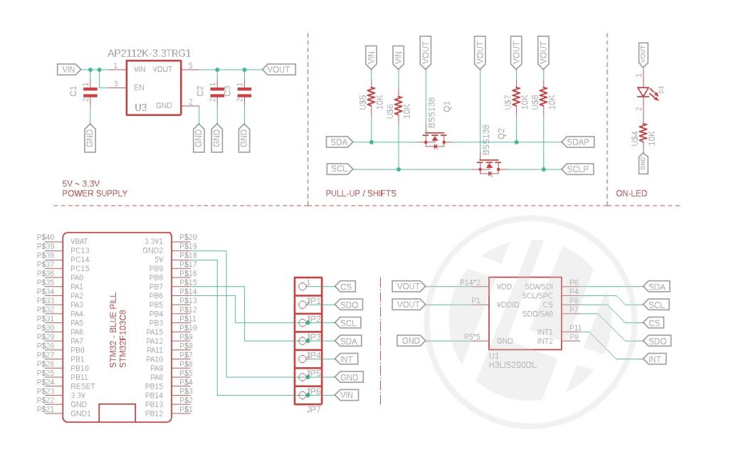
- Note: The Diagram below is using STM32 Blue Pill / STM32 Black Pill (please refer to your MCU’s respective pin-outs & bus configuration)
- H3LIS200DL Angle Sensor
- Resistors (See below diagram for required value & alternatives package)
- Capacitor(See below diagram for required value & alternatives package)
Wiring Diagram / Schematics
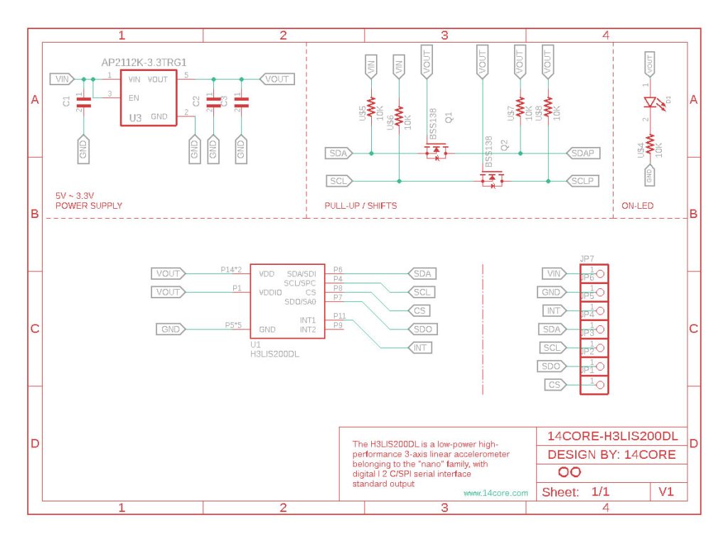
14CORE-H3LIS200DL Schematics Diagram
As you can see in the above schematics it is place an PullUp and Shift. pull-up resistors are required on both the SDA (data) and SCL (clock) lines pins to ensure reliable communication. The pull-up resistors keep the lines at a high logic level when they are not being actively driven by the I2C master or slave device.
The value of the pull-up resistors depends on the capacitance of the I2C bus, the maximum communication speed, and the number of devices connected to the bus. Generally, a value between 1 kΩ and 10 kΩ is used for the pull-up resistors.
In some cases, it may be necessary to use a MOSFET to shift the voltage levels of the I2C signals to match the voltage levels of the master or slave devices. This is typically required when the I2C devices have different voltage levels or when there is a long distance between the devices.
To use a MOSFET for voltage level shifting in an I2C bus, you can connect the MOSFET’s gate to the I2C signal, the source to the ground, and the drain to the higher voltage supply. When the I2C signal is high, the MOSFET will be turned on, allowing the signal to pass through. When the I2C signal is low, the MOSFET will be turned off, isolating the signal from the higher voltage supply.
It is important to choose a MOSFET with a low on-resistance and a threshold voltage that is compatible with the I2C signal levels. The MOSFET should also have a low gate capacitance to minimize any signal distortion or delays.
Overall, pull-up resistors are necessary for reliable I2C communication, while MOSFETs can be used for voltage level shifting when required. It is important to carefully design and test the I2C circuit to ensure reliable communication between the devices.
Sketch Code
Python Code
Gerber File & Part List

- Download PCB Milling File | H3LIS200DL
- Download Gerber Viewer | Windows | Linux


