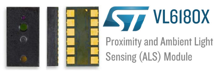
This is the ST”s Single Package VL6180X Proximity and Ambient Light Sensor that measures a range to a target object distance up to 20-centimeter or 60-centimeter range by reducing the resolution. The VL61850X uses TIME-TO-FLIGHT measurements with the use of infrared pulses for ranging, which delivers an accurate result independent of the color and surface of the target. Moreover, the distance and ambient light level measurements can be captured through the i2c(TWI) digital interface, compare to other optical proximity sensors, some sensor uses the intensity of reflected light to detect an object, whereas the VL6180 uses ST’s patented FlightSense technology to precisely measure how long it takes for emitted pulses of infrared laser light to reach the object and reflected back a detector, similar to a short-range LIDAR (Light Detection and Ranging) sensor.

The TOF (Time-Of-Flight) allows one to accurately determine the distance to a target within 1 mm resolution without the barrier reflectance affecting the measurement. This sensor is rated to perform a range of up 10 centimeters, however, it can often give a reading of up to 20cm with its factory settings. Furthermore, the ST’s VL6180X can be set to measure ranges of up to 60 cm by reducing the resolution. however, thriving at this longer distance will depend on the target and ambient. The VL6180 also includes an ambient light sensor, that can measure the light intensity which is illuminated. Ranging and ambient light readings are available through the i2C bus interface which is also used to configure the settings of the sensor, and two GPIO pins to set independently programmed and configure as interrupt outputs. These ST’s VL6180X is a great small-size leadless land grid array package it quite difficult to use. however, there are some videos available that you can mount the LGA package to a pre-holed prototyping PCB board but using 1/4 resistors and SMD capacitors.
The ST’s VL6180X operates at a voltage of 3v, making interfacing difficult for microcontrollers to operate at 3.3v or 5v. our schematics handle these issues and make it easier to get started using the sensor while maintaining the most comprehensive sizes possible.
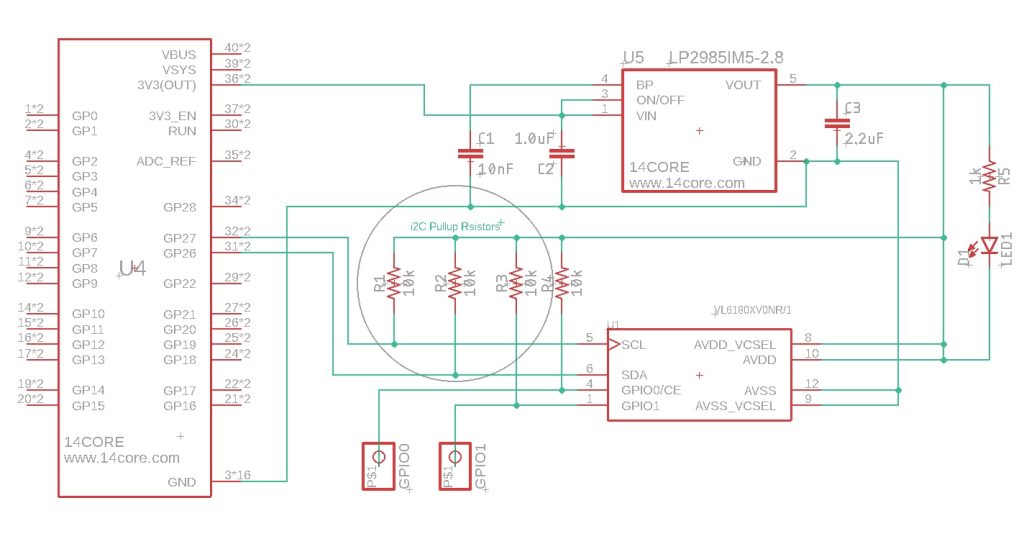
As you can see from the schematics we used a Low-dropout Linear Voltage Regulator that provides a 2.8v as the requirement for the VL6180X, which allows us to drive the sensor to be powered from a 2.7 volts to 5.5 volts supply or getting the supply voltage from the microcontroller. For important technical details including the RANGE SCALING FACTOR Please see the datasheet bellow.
Requirements
- Arduino IDE | PlatformIO
- Test Boards :
- Note: The Diagram below is using Raspberry Pi PICO (please refer to your MCU’s respective pin-outs & bus configuration)
- Resistors (See below diagram for required value)
- Regulator (See below diagram for required value)
- Capacitor(See below diagram for required value)
- Resistors (See below diagram for required value)
- LED (SMD)
Wiring Diagram & Schematics
Sketch Source Code
CircuitPython
MicroPython
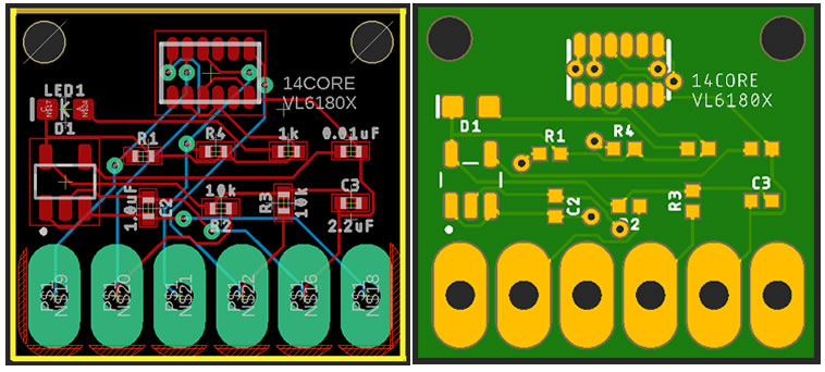
PCB Board Milling / Gerber File

Downloads
- Download the ST’s VL6180X Datasheet | PDF
- Download VL6180X Sample Codes | Zip
- Download VL6180X Arduino Code Library | Zip
- Download VL6180X CircuitPython | Zip


