ESP8266 is capable to transmit and receive data via WiFi. ESP8266 can be configured or set as a basic server and access point. On this guide, we will be going to configure the ESP8266 to talk to each other without the help of the network router. As you can see the illustration there will be two devices act as INPUT and OUTPUT the INPUT will be the sensor and the OUTPUT will the OLED display module and the sensor we will going used for this demonstration is the Microchip MCP9808 temperature sensor.
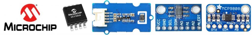
The Microchip MCP9808 temperature sensor is driven by i2c that can sense temperature between -20°C ~ +100°C converted to digital signals integrated accuracy of ±0.25°C/±0.5°C (typical/maximum). The MCP9808 temperature sensor is flexible the registers featuring a selectable configuration such as shutdown or low-power modes, temperature alerts, and critical output limits when the temperature changes the limits the sensor can send an alert signal to the MCU this is feature is an advantage to managing cooling systems. For more readings about the MCP9808 please refer to the datasheet below.
Required Component for this Lab
- Arduino IDE | Atmel Studio | Energia | Processing
- ESP8266 / ESP32 Module or Board
- MCP9808 Sensor /Module
- Capacitors (See below required value)
- Resistors (See below required value)
- TTL USB UART (Optional if your using s MCU USB/UART integrated)
- PCB Designer (Circuit simulator to PCB Layout / Circuitmaker / Autodesk Eagle / Fritzing )
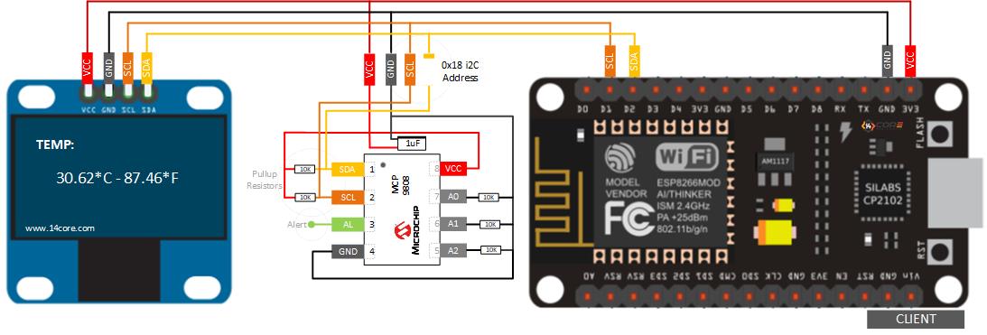
Wiring Guide for the Station / Client
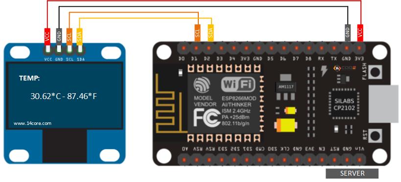
Wiring Guide for the Access Point / Server
Source Code for the Client
Source Code for the Server
Downloads and Datasheets
- Guide for the SSD1306 128X64 OLED Display Module
- Download the SSD1306 128X64 OLED Display Library here
- Download the MCP9808 Code Library
- Download the MCP9808 Temperature Sensor Datasheet


