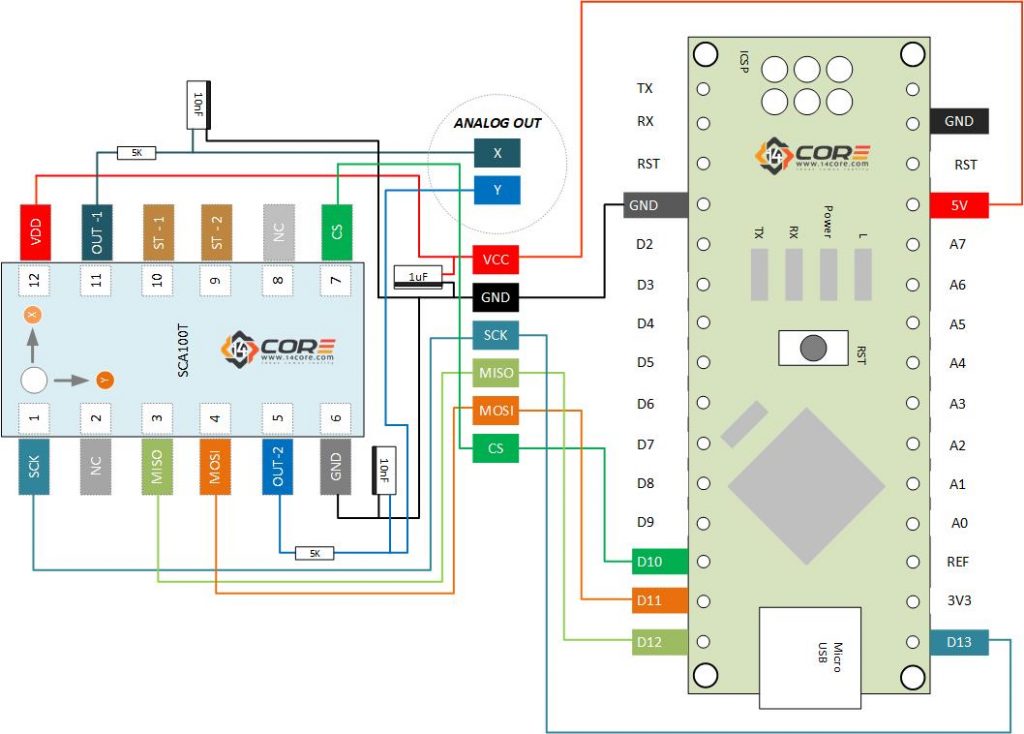
This is the SCA100T a dual axis inclinometer sensor a series of a 3D micromechanical based. This device has integrated based axis inclinometer that delivers an instrumentation grade performance for leveling applications. The measuring axes of the sensing elements are parallel to the mounting plane and orthogonal to each other. The SCA100T has a low temperature dependency, high resolution and low noise, with a sensing element architecture and un-sensitive to vibration due to their over damped sensing elements and can withstand mechanical shocks up to 20000 grams. This device runs on 5v with ratio metric analog voltage outputs and Communicate using SPI (Serial Peripheral Interface). As you can see the wiring diagram below the sensor is driven by NANO microcontroller just for this example you can use AVR, STM32, or ESP8266/ESP32 for testing. The SCA100T should be powered from regulated 5V DC with coupler to minimize the noise we used 1uf for filtering capacitor between the VDD and GND you can also use 470pF or 100nf capacitor. And for the RF filters we use 5k and 10uf on pin OUPUT to minimize the clock noise. This device can be use in Platform leveling and stabilization, 360 Degree vertical orientation measurement, Leveling Struments, Construction Levels, Building Automations, Industrial Automations, Medical & Laboratory Equipment. Etc. For more reading and introduction about inclinometer refer to this link and for the SCA100T datasheet you can see get it below.
Required Components
- Arduino IDE | Atmel Studio | Energia | Processing
- Arduino PRO, FIO, NANO, UNO, MINI, MEGA, PRO MINI, LEO, BT, DUE, ETHERNET,LILYPAD, NodeMCU, Teensy Board, TeensyDuino, ESP8266 12, 12E, ESP32, LinkItOne, ESP8266 NodeMCU, ESPDuino, ATMEGA328 16/12, ATMEGA32u4 16/8/ MHz, ESP8266, MSP430 ,ATMEGA250 16 MHz, ATSAM3x8E, Note: The Diagram below is using NANO. (please refer to each MCU’s respective pin-outs & bus configurations)
- MURATA SCA100T Dual Axis Inclinometer Sensor / SCA100T Module
- Capacitors (See below required values)
- Resistors (See below required values)
- Jumper Wire (Optional)
- PCB Designer (Circuit simulation to PCB Layout)
Wiring Guide
Source


Hi,
Your sample code does not work.
It does not compile in the arduino IDE because there are missing “;”
MISO and MOSI lines are reversed (MOSI is pin 11 and MISO is pin 12, you have it the other way around)
After fixing these, I could not get it to work still.
Could you provide any guidance/provide working code.
Error in code, you can help?
line56
Serial.println(AX);→Serial.println(senseX);
line 58
Serial.println(AY);→Serial.println(senseY);
On Arduino output only values 2047 and 0 appear, even if you move the sensor
Read value of X >
2047
Read value of Y >
2047
Read value of X >
0
Read value of Y >
0