Henri Coderre at Permalink The 2.2uF electrolytic capacitor is missing the negative connection. Can you tell me what this connects to? Reply
Henri Coderre at Permalink PCA9685 pin 23 is OE. Schematic shows it as PW15 and considers it to be a PWM. If I count the number of servo connectors I get 17 when there should only be 16! If these have been corrected please let me know. Reply
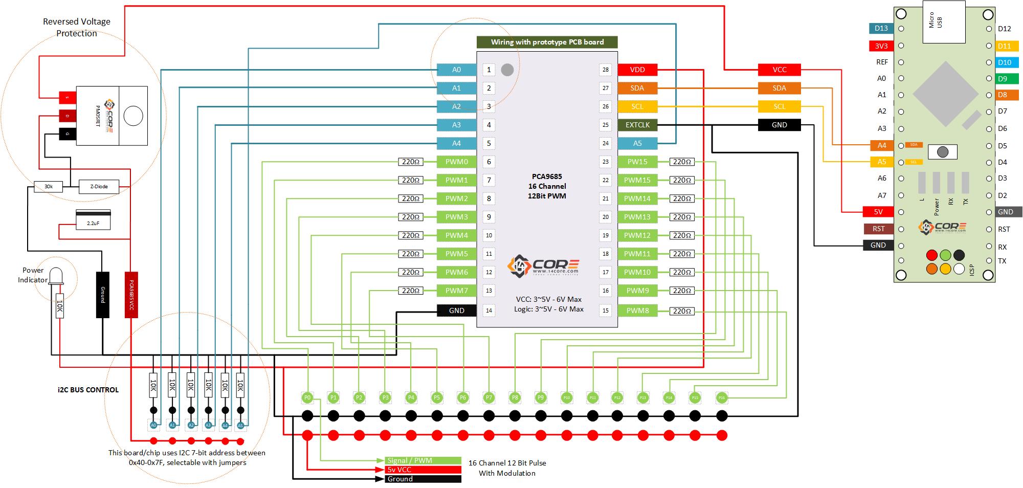


The 2.2uF electrolytic capacitor is missing the negative connection. Can you tell me what this connects to?
PCA9685 pin 23 is OE. Schematic shows it as PW15 and considers it to be a PWM. If I count the number of servo connectors I get 17 when there should only be 16! If these have been corrected please let me know.
Updated, Capacitor should in GND/Ground. Cheers!!!