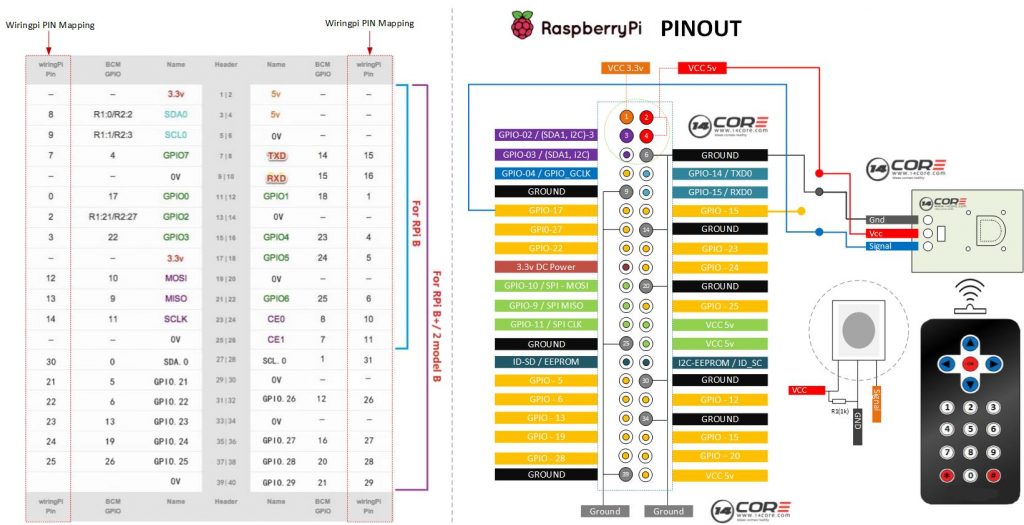
Another illustration demonstrating how IR Emission works on Raspberry Pi, for introduction how IR Emission works please refer to this link. IR (Infrared Receiver) is a device / component which receives IR signals and can independently receive IR rays and output signals also compatible with TTL level compatible for all kinds of infrared remote control or infrared transmission. The goal of this experiment is to receive and send signal when remote infrared transmission are pressed.
Component Required
- Raspberry Pi / Banana Pi / Orange Pi (If your using Banana Pi or Orange Pi See first the GPIO Pins)
- IR Receiver Module / NEC IR 38k IR / VS1838 / AX1838HS
- 1k Resistor (Optional if your using IR Module)
- Solder Less Bread Board
- Jumper Wire / DuPont Wire
Wiring Guide
C-Source Code
1 2 3 4 5 6 7 8 9 10 11 12 13 14 15 16 17 18 19 20 21 22 23 24 25 26 27 28 29 30 31 32 33 34 35 36 37 38 39 40 41 42 43 44 45 46 47 48 49 |
/* 14CORE Test Code for: IR RX TEST CCODE .:+osysso++:` `+yhs/-` `-+s+` `:/+++++++++` .:/++ooo++/-` .ooooooooooo+: :///////////- `odh/` `:y+` /ddhsooooooo+ /hddhsooooydddh sdddoooooosdddy` `////////////` -hds` `sy. +ddy` .ddd: sddy.dddo +ddd- .-----------` `hds :sssss/ -ossssso-yy` `hdd: oddy `ddd/oddd:......+dddo .++++++++++++ +dd` :sdddh` :ydddddddo +y/ .ddd+........ `hddy:.....:yddy.hdddddddddddy+. ```````````` ydy .hddd/+hdddhydddh/.+yo /hdddddddddd. :shddddddddhs/`+ddd:````-yddy- :ooooooooooo+ odh` sdddooyyyyyhddddyy.sy+ ` `......... ``.... ....` ```...` ` `` `` ` -dd+`::::` .:::- /yy. -oos+:-oos+--oos+: /o `+y o/: o:+/ h:`yos /+-`/+/+ s:y/y. /dd/ `+yy: +//+ +/:+ +/:+ -. `/ -:o.:/:`//+- + +:- :`-+:`://: +`o`+. -yds. `/yys- .`-.. .``` ```` .`` ` ` ``` ``-..` ` :ydy/.`````.-/oyhs: `+++oo+oo+:.+-++/-/ooo+o +:o/oo///:+/ .:oyhhhhhhhso:` `. ``` */ #include <wiringPi.h> #include <stdio.h> #define IR 0 int cnt = 0; void IRRX(void) { printf("Signal Received. cnt = %d\n", ++cnt); } int main(void) { if(wiringPiSetup() == -1){ //If no response from wiringpi.h print printf("Wiring Pi Initialization Faild"); return 1; } if(wiringPiISR(IR, INT_EDGE_FALLING, &IRRX) == -1){ printf("IR failed no response!"); return 1; } //pinMode(IR, INPUT); while(1); return 0; } |
Python Source Code
1 2 3 4 5 6 7 8 9 10 11 12 13 14 15 16 17 18 19 20 21 22 23 24 25 26 27 28 29 30 31 32 33 34 35 36 37 38 39 40 41 42 43 44 45 46 |
# 14CORE Test Code for: IRRX Python Test Code # .:+osysso++:` # `+yhs/-` `-+s+` `:/+++++++++` .:/++ooo++/-` .ooooooooooo+: :///////////- # `odh/` `:y+` /ddhsooooooo+ /hddhsooooydddh sdddoooooosdddy` `////////////` # -hds` `sy. +ddy` .ddd: sddy.dddo +ddd- .-----------` # `hds :sssss/ -ossssso-yy` `hdd: oddy `ddd/oddd:......+dddo .++++++++++++ # +dd` :sdddh` :ydddddddo +y/ .ddd+........ `hddy:.....:yddy.hdddddddddddy+. ```````````` # ydy .hddd/+hdddhydddh/.+yo /hdddddddddd. :shddddddddhs/`+ddd:````-yddy- :ooooooooooo+ # odh` sdddooyyyyyhddddyy.sy+ ` `......... ``.... ....` ```...` ` `` `` ` # -dd+`::::` .:::- /yy. -oos+:-oos+--oos+: /o `+y o/: o:+/ h:`yos /+-`/+/+ s:y/y. # /dd/ `+yy: +//+ +/:+ +/:+ -. `/ -:o.:/:`//+- + +:- :`-+:`://: +`o`+. # -yds. `/yys- .`-.. .``` ```` .`` ` ` ``` ``-..` ` # :ydy/.`````.-/oyhs: `+++oo+oo+:.+-++/-/ooo+o +:o/oo///:+/ # .:oyhhhhhhhso:` `. ``` #!/usr/bin/env python import RPi.GPIO as GPIO MYIRPIN = 11 COUNT = 0 def setup(): GPIO.setmode(GPIO.BOARD) # Set GPIO as Number GPIO.setup(MYIRPIN, GPIO.IN, pull_up_down=GPIO.PUD_UP) def cnt(ev=None): global COUNT COUNT += 1 print 'Signal Received. cnt = ', COUNT def loop(): GPIO.add_event_detect(MYIRPIN, GPIO.FALLING, callback=cnt) # wait for falling while True: pass # Dont do anything def destroy(): GPIO.cleanup() # Resource Release if __name__ == '__main__': # Start Program setup() try: loop() except KeyboardInterrupt: # When Control C is pressed program will destroy destroy() |
Wiring The AX1838HS / VS1838 / NEC-IR 38K IR on Raspberry Pi
Bedankt voor de post helpt me op mijn school projecten. meer macht aan u 14core. keep it up.