Linear Sensor are critical to the performance to their sensitivity and linearity over their specified operating temperature range and immune to most environmental disturbance that may affect optical or mechanical devices, such as vibration, moisture, dirt or oil films, ambient, lightning, etc.
Linear Hall Effect Sensor are commonly used in current sensing, power sensing (watt-hour-metering), current trip-point detection, strain gauge, biased (magnetically) sensing applications, Ferrous metal detection, proximity sensing, Joy-Stick with intermediate positions sensing, liquid-level sensing, temperature / pressure / vacuum sensing, throttle or air valve positions sensing, non-contact potentiometers, etc.
Components Required
- Raspberry Pi / Banana Pi / Orange Pi (If your using Banana Pi or Orange See first the GPIO Pins)
- Hall Effect Sensor
- LED (Any Color)
- 220 Ohms Resistor
- Solder Less Bread Board
- Jumper Wire / DuPont Wire
- 10k Resistor (Optional)
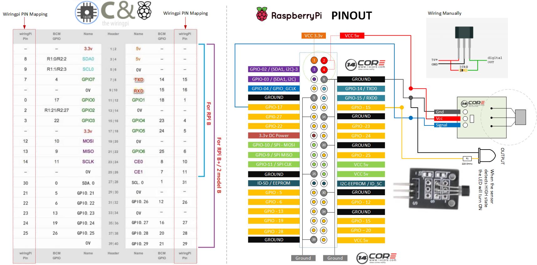
Wiring Diagram

For C Code
For Python Code


Pingback:Wiring the 14CORE 37 Sensors for Arduino & Raspberry Pi | 14Core.com
You show the output of the 3144 Hall sensor pulled up to +5 Volts and then connected to GPIO17.
Be aware that the GPIO pins of a Raspberry Pi are not 5 volt tolerant. You should never connect them to +5 Volts! Many people have done this. Many people have damaged their Pi.
Remove the 10k resistor and use the internal GPIO pullup to power the open collector output of the Hall sensor.
But never, ever, connect a GPIO pin to +5 Volts.