Another illustration how to build a simple physical intrusion detection with laser and photoresistor (or light-dependent resistor, LDR, or photocell). This guide shows how to wire and build a laser tripwire that triggers an alarm or output when the laser is interrupted with any objects that pass. As you can see the diagram below it uses a module for this demonstration. There are two options to be followed here one is wiring manually and two wiring together with the prebuild modules. See the illustration below.
Components Required for Assembly
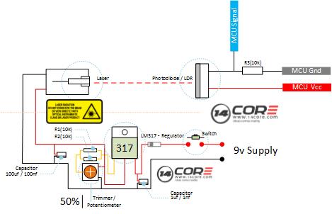
- ESP8266 Boards / Arduino Boards / Raspberry Pi / AVR
- Laser Valve
- LDR / Photodiode
- 10k Resistors
- 1 uf Capacitor
- 100 uf Capacitor
- Power Diode
- Trimmer / Potentiometer
- Solderless Breadboard / PCV Board
- Jumper Wires
- LED
- 220 Ohms Resistor
- Buzzer (Optional)
Wiring Diagram for Assembly
Components required for module
- ESP8266 Boards / Arduino Boards / Raspberry Pi / AVR
- Laser Valve Light Transmitter Module
- LDR / Photodiode Module
- Solderless Bread Board
- Jumper Wire / DuPont Wire
- LED
- 220 Ohms Resistor (For Pin 13 you dont need to place a resistor)
- Buzzer (Optional)
Wiring Diagram for Module

Source Code / Sketch Code
Wiring The Laser Transmitter on Photocell with Microcontroller


Pingback:Wiring the 14CORE 37 Sensors for Arduino & Raspberry Pi | 14Core.com