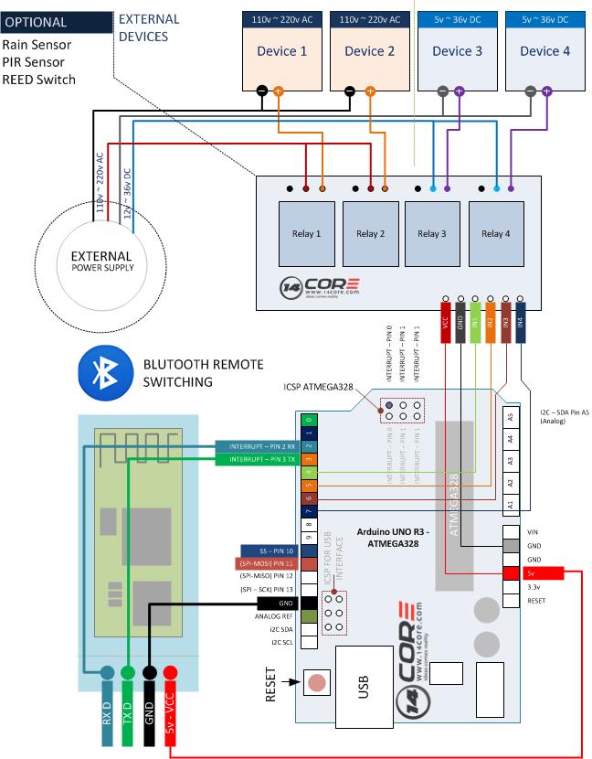
In this illustration we will going to wire the HC-04,HC-05 or HC-06 module using serial communication with our Arduino board and 4 channel relay, we will going to control the relay on the Android smart phone or tablet via Bluetooth to control the relay remotely. See the illustration below for wiring all the required components. as our output device we will just see the LED status from the relay module, anyway you can plug any device to the relay like lights, home appliances or any device as you want that can be switch on.

Required Components
- Arduino Board
- Bluetooth Serial Module Board
- 4 Channel Relay Module Board
- Solder Less Bread Board
- Jumper Wires / DuPont Wires
Wiring Diagram
Arduino Sketch
|
1 2 3 4 5 6 7 8 9 10 11 12 13 14 15 16 17 18 19 20 21 22 23 24 25 26 27 28 29 30 31 32 33 34 35 36 37 38 39 40 41 42 43 44 45 46 47 48 49 50 51 52 53 54 55 56 57 58 59 60 61 62 63 64 65 66 67 68 69 70 |
/* ####################################################### */ //********************************************************** // 14CORE Sample Test code for Bluetooth Home Automation // www.14core.com / //********************************************************** //* $$$$$$$$$$$$$$$$$$$$$$$$$$$$$$$$$$$$$$$$$$$$$$$$$$$$$$ */ #include <SoftwareSerial.h> //Serial Communicaton at IDE Code Library SoftwareSerial mySerial(2, 3); //Set serial communication digital pin 2 for RX & digital pin 3 for TX int channel1 = 4; //Assign Relay Channel 1 to Digital pin 4 int channel2 = 5; //Assign Relay Channel 2 to Digital pin 5 int channel3 = 6; //Assign Relay Channel 3 to Digital pin 6 int channel4 = 7; //Assign Relay Channel 4 to Digital pin 7 void setup() { mySerial.begin(9600); //Start Serial Communication at Baud rate 9600 //Micro controller pinMode(channel1, OUTPUT); //Arduino Digital Pin 4 for Relay Channel 1 pinMode(channel2, OUTPUT); //Arduino Digital Pin 5 for Relay Channel 2 pinMode(channel3, OUTPUT); //Arduino Digital Pin 6 for Relay Channel 3 pinMode(channel4, OUTPUT); //Arduino Digital Pin 7 for Relay Channel 4 // Relay digitalWrite(channel1,HIGH); //Digital write state Pin 4 mode turn to HIGH digitalWrite(channel2,HIGH); //Digital write state Pin 5 mode turn to HIGH digitalWrite(channel3,HIGH); //Digital write state Pin 6 mode turn to HIGH digitalWrite(channel4,HIGH); //Digital write state Pin 7 mode turn to HIGH } void loop() { char Char_string = mySerial.read(); //RELAY CHANNEL 1 if(Char_string == 'A') //MCU reads char string = A set relay channel 1 turn to LOW { digitalWrite(channel1,LOW); //Relay channel 1 turn LOW } if(Char_string == 'B') //MCU reads Char String = B set relay channel 1 turn to HIGH { digitalWrite(channel1,HIGH); //Relay channel 1 turn HIGH } // RELAY CHANNEL 2 if(Char_string == 'C') //MCU read char string = C set relay channel 2 turn to LOW { digitalWrite(channel2,LOW); //Relay channel 2 turn LOW } if(Char_string == 'D') //MCU read char string = D set relay channel 2 turn to HIGH { digitalWrite(channel2,HIGH); //Relay channel 2 turn HIGH } // RELAY CHANNEL 3 if(Char_string == 'E') //MCU reads char string = E set relay channel 3 turn to LOW { digitalWrite(channel3,LOW);//Relay channel 3 turn LOW } if(Char_string == 'F') //MCU reads char string = F set relay channel 3 turn to HIGH { digitalWrite(channel3,HIGH);//Relay channel 3 turn HIGH } // RELAY CHANNEL 4 if(Char_string == 'G') //MCU reads char string = G set relay channel 4 turn to LOW { digitalWrite(channel4,LOW); //Relay channel 4 turn LOW } if(Char_string == 'H') //MCU read char string = H set relay channel 4 turn to HIGH { digitalWrite(channel4,HIGH); //Relay channel 4 turn HIGH } delay(10); //Delay @ 10 seconds } |
Android App
Download the android application here | Zip
Bluetooth Home Automation with Arduino and Android


It’s not working……….. how to slove?? I was upload your program but its not working.
Use this instead.
http://www.14core.com/wiring-bluetooth-hc06-in-8-channel-relay-with-android-arduino-microcontroller/
or This
http://www.14core.com/wiring-bluetooth-hc06-4-channel-relay-switching-automation-with-android/