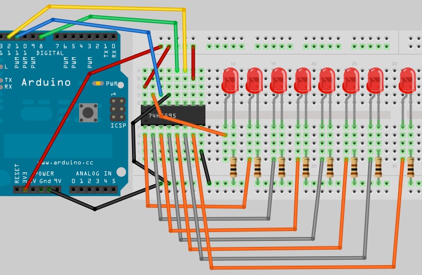
On this illustration we will going to drive and wire the 74HC595 on a shift register using our very own Arduino Board, The 74HC595 is high speed si-gate CMOS(Complementary Metal Oxide Semiconductor) integrated circuit device the pin is compatible with low-power Scottky TTL (LSTTL). The 74HC595 are 8 stage serial shift register with storage register and it has 3 state output. The register have separate clocks. Data is shifted on the positive going transitions of the SHCP(shift register clock inputs). The data is each register is transferred to the storage register on a positive going transition of the STCP (storage register clock inputs). If both clocks are connected together, the shift register will always be one clock pulse ahead of the storage register. The shift register has also DS (serial input) and a Q7S ( serial standard output) for cascading. It is also provided with asynchronous reset (active LOW) for all 8 shift register stages. The storage register has 8 parallel 3 state bus driver output. Data in the storage register appears at the output whenever the OE (output enable) input is LOW.
Required Components
1x 74HC595 Shift Register
8x 240 Ohms Resistor
8x LED at any color
The 74HC595 Pin-Out Diagram
Wiring the 74HC595 to Arduino Board
The Arduino Sketch Code
1 2 3 4 5 6 7 8 9 10 11 12 13 14 15 16 17 18 19 20 21 22 23 24 25 26 27 28 29 30 31 32 33 34 35 36 37 38 39 40 41 42 43 |
/* 14CORE TEST Sketch For 8Bit Shift Register Binary Counter */ int latchPin = 8; //Pin connected to Pin 12 of 74HC595 (Latch) int clockPin = 12; //Pin connected to Pin 11 of 74HC595 (Clock) int dataPin = 11; //Pin connected to Pin 14 of 74HC595 (Data) void setup() { //set pins to output pinMode(latchPin, OUTPUT); pinMode(clockPin, OUTPUT); pinMode(dataPin, OUTPUT); } void loop() { for (int i = 0; i < 256; i++) { //count from 0 to 255 digitalWrite(latchPin, LOW); //set latchPin low to allow data flow shiftOut(i); digitalWrite(latchPin, HIGH); //set latchPin to high to lock and send data delay(500); } } void shiftOut(byte dataOut) { boolean pinState; // Shift out 8 bits LSB first, on rising edge of clock digitalWrite(dataPin, LOW); digitalWrite(clockPin, LOW); for (int i=0; i<=7; i++) { // for each bit in dataOut send out a bit digitalWrite(clockPin, LOW); //set clockPin to LOW prior to sending bit if ( dataOut & (1<<i) ) { // if the value of DataOut and (logical AND) a bitmask are true, set pinState to 1 (HIGH) pinState = HIGH; } else { pinState = LOW; } digitalWrite(dataPin, pinState); //sets dataPin to HIGH or LOW depending on pinState digitalWrite(clockPin, HIGH); //send bit out on rising edge of clock } digitalWrite(clockPin, LOW); //stop shifting out data } |
Download the 74HC595 Datasheet here | Pdf