


This is the FE1.1s chip a USB 2.0 hub controller chip developed by a company called Fortune Semiconductor Corporation. This chip is designed to provide additional USB ports to devices, allowing users to connect multiple USB devices to a single USB port on their computer or other devices.
This chip was first released by the Taiwanese company Fortune Semiconductor Corporation (FSC) in 2012. It was designed to provide a low-cost and compact USB 2.0 hub solution for a variety of applications, including laptops, desktops, and embedded systems. The chip was well-received in the market due to its small form factor, low power consumption, and cost-effectiveness. These features made it an ideal solution for devices that required multiple USB ports, such as portable devices, docking stations, and other peripherals.
Over time, the FE1.1S chip has become a popular choice for USB hub applications, and it has been widely adopted by many electronics manufacturers around the world. Today, it remains a popular choice for adding USB connectivity to a wide range of devices, and it continues to be a key component in many USB hub designs.
Technical specifications of the FE1.1S chip:
- USB 2.0 compliant
- Single-chip USB hub controller
- Supports 4 downstream USB ports
- Integrated upstream USB transceiver
- Built-in 1.5K ohm pull-up resistor for USB port detection
- Supports low-speed, full-speed, and high-speed USB devices
- Supports data transfer rates of 1.5/12/480 Mbps
- Over-current detection and protection on each downstream port
- 3.3V operating voltage
- Available in QFN-28 package
In addition, the FE1.1S chip has a small form factor of 5mm x 5mm, making it ideal for applications where space is limited. The chip also consumes low power, which is beneficial for battery-powered devices. Its compatibility with multiple USB devices and its low cost has made it a popular choice for USB hub applications.
FE1.1S chip requires a single 3.3V power supply and can operate over a temperature range of -40°C to +85°C. To implement the FE1.1S chip in a PCB design, there are a few things to consider:
- Power Supply: The FE1.1S chip requires a stable 3.3V power supply. It is important to ensure that the power supply is capable of providing enough current to power the chip and any connected USB devices.
- Layout: The layout of the FE1.1S chip on the PCB should be carefully designed to ensure proper signal integrity and minimize noise. The USB traces should be kept as short as possible and should be routed away from other high-speed signals.
- Decoupling Capacitors: Decoupling capacitors should be placed as close as possible to the power supply pins of the FE1.1S chip to ensure stable operation and minimize noise.
- ESD Protection: To protect the FE1.1S chip from electrostatic discharge (ESD) damage, it is recommended to add ESD protection devices to the USB data lines.
- USB Connectors: The USB connectors should be carefully selected to ensure compatibility with the FE1.1S chip and the connected USB devices. It is recommended to use shielded connectors to minimize noise and EMI.
- Grounding: Proper grounding is important to ensure proper operation of the FE1.1S chip and any connected USB devices. It is recommended to use a solid ground plane and to connect the ground pins of the USB connectors directly to the ground plane.
To design a product that uses FE1.1S chip in a PCB, it is important to consider the power supply, layout, decoupling capacitors, ESD protection, USB connectors, and grounding. Careful design and attention to these details can help ensure proper operation and compatibility with a wide range of USB devices.
list of applications this device can be used:
- Set-Top Boxes: Set-top boxes are used to receive and decode digital television signals. The FE1.1S chip can be used in set-top boxes to provide additional USB ports, making it easier for users to connect USB storage devices or other accessories to the set-top box.
- Smartphones and Tablets: Some smartphones and tablets come with a single USB port, which is used for charging and data transfer. By using the FE1.1S chip, manufacturers can add additional USB ports to the device, making it easier for users to connect USB storage devices, keyboards, mice, and other accessories.
- Network Devices: Network devices such as routers and switches often require multiple USB ports for connecting to USB storage devices or other accessories. By using the FE1.1S chip, manufacturers can provide additional USB ports, making it easier for users to connect their devices to the network.
- Audio Devices: Audio devices such as speakers and headphones can benefit from additional USB ports, which can be used to connect other audio devices or USB storage devices. The FE1.1S chip can be used to provide additional USB ports, making it easier for users to connect all of their audio devices.
- Medical Devices: Medical devices such as blood glucose meters and heart rate monitors often require a USB connection for data transfer. By using the FE1.1S chip, manufacturers can add additional USB ports to the device, making it easier for healthcare professionals to connect the device to a computer or other device.
- Automotive: The FE1.1S chip can be used in automotive applications, where it can provide additional USB ports for charging smartphones or tablets. This can be especially useful in newer cars that come with only one or two USB ports.
- Industrial Control Systems: The FE1.1S chip can be used in industrial control systems to provide additional USB ports for connecting industrial devices, such as sensors or other monitoring equipment. This can make it easier to collect and analyze data from these devices.
- Home Automation: The FE1.1S chip can be used in home automation systems to provide additional USB ports for connecting various devices, such as smart locks, smart thermostats, and other home automation devices. This can make it easier for users to control and manage their home automation systems.
- Point of Sale (POS) Systems: POS systems often require multiple USB ports for connecting peripherals such as barcode scanners, credit card readers, and cash drawers. The FE1.1S chip can be used in POS systems to provide additional USB ports, making it easier to connect these peripherals.
- Digital Signage: Digital signage often requires a USB connection for content updates or to provide power to the display. The FE1.1S chip can be used to provide additional USB ports, making it easier to connect multiple digital signage displays to a single computer or other devices.
- Gaming Consoles: Gaming consoles often require multiple USB ports for connecting controllers, headsets, and other gaming accessories. The FE1.1S chip can be used in gaming consoles to provide additional USB ports, making it easier for gamers to connect all of their accessories.
- Security Systems: Security systems such as CCTV cameras and door access control systems often require a USB connection for data transfer. The FE1.1S chip can be used in security systems to provide additional USB ports, making it easier for security professionals to connect their devices to a computer or other device.
- Robotics: Robotics applications often require a USB connection for programming and data transfer. The FE1.1S chip can be used in robotics applications to provide additional USB ports, making it easier to connect multiple robotic devices to a single computer or other devices.
- Drones: Drones often require a USB connection for data transfer and firmware updates. The FE1.1S chip can be used in drones to provide additional USB ports, making it easier for users to connect their drones to a computer or other device.
- Wearable Devices: Wearable devices such as smartwatches and fitness trackers often come with a single USB port, which is used for charging and data transfer. By using the FE1.1S chip, manufacturers can add additional USB ports to wearable devices, making it easier for users to connect other accessories.
- Education: The FE1.1S chip can be used in educational settings, where it can provide additional USB ports for connecting educational devices such as microscopes, sensors, and other scientific equipment. This can make it easier for students and teachers to conduct experiments and collect data.
This chip can be implemented in a wide range of electronic devices and applications, where it can provide additional USB ports and make it easier for users to connect their devices and accessories. Its versatility and compatibility with various devices and systems have made it a popular choice for USB hub applications in numerous industries. If you have any questions about the design or any feedback please let us know to enhance and find this device more useful, additionally please refer to the technical details about this chip located below at the download section.
Requirements & Parts List
| PART | VALUE | PACKAGE |
| C1,C2,C3 | 10uF | 0603CAPS |
| C4 | 0.1uF | 0603CAPS |
| D1, D2,D3,D4,D5 | KPT-1608ZGC | LED_KPT-1608ZGC |
| IC1 | FE1.1S | SOP64P600X175-28 |
| J2 | TYPE-C-31-M-12 | TYPE-C-31-M-12 |
| Q1 | 12HMz Crystal | QS |
| R1,R2 | 5.3K | 0603RES |
| R3,R5,R6,R7,R8 | 220 | R0603 |
| R4 | 2.7K | R0603 |
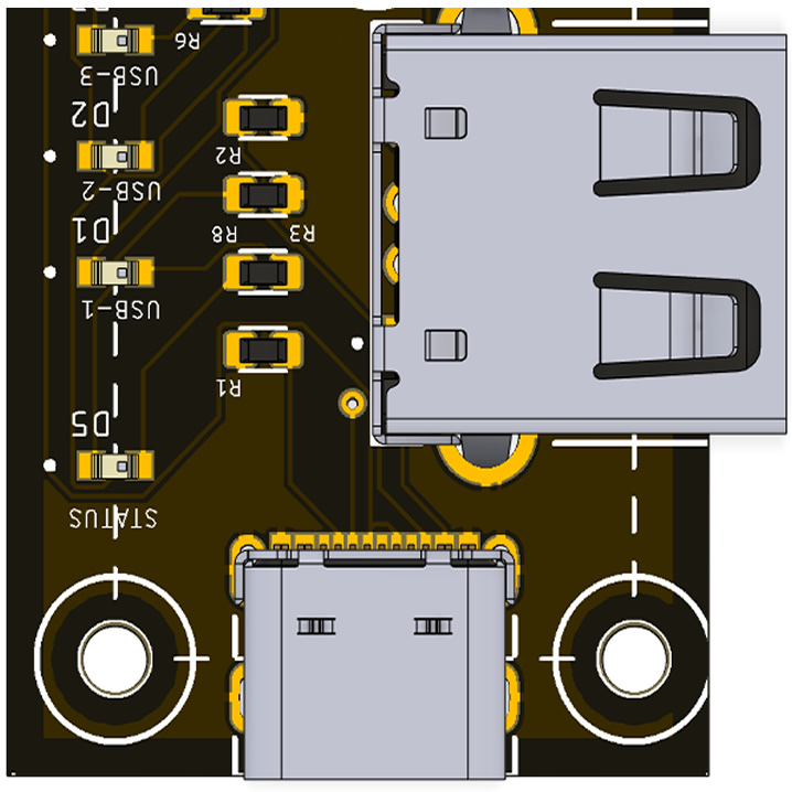
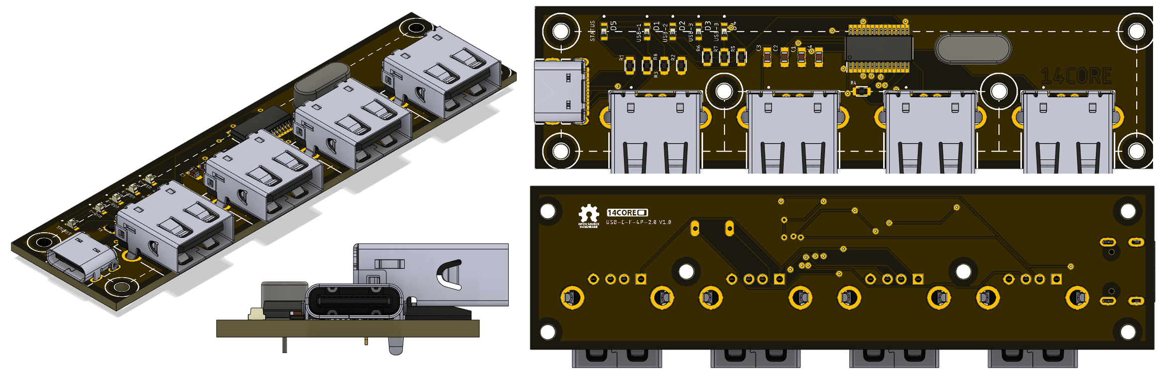
| USB1,USB2,USB3,USB4 | USB1130-15-A_REVA | GCT_USB1130-15-A |
Schematics:
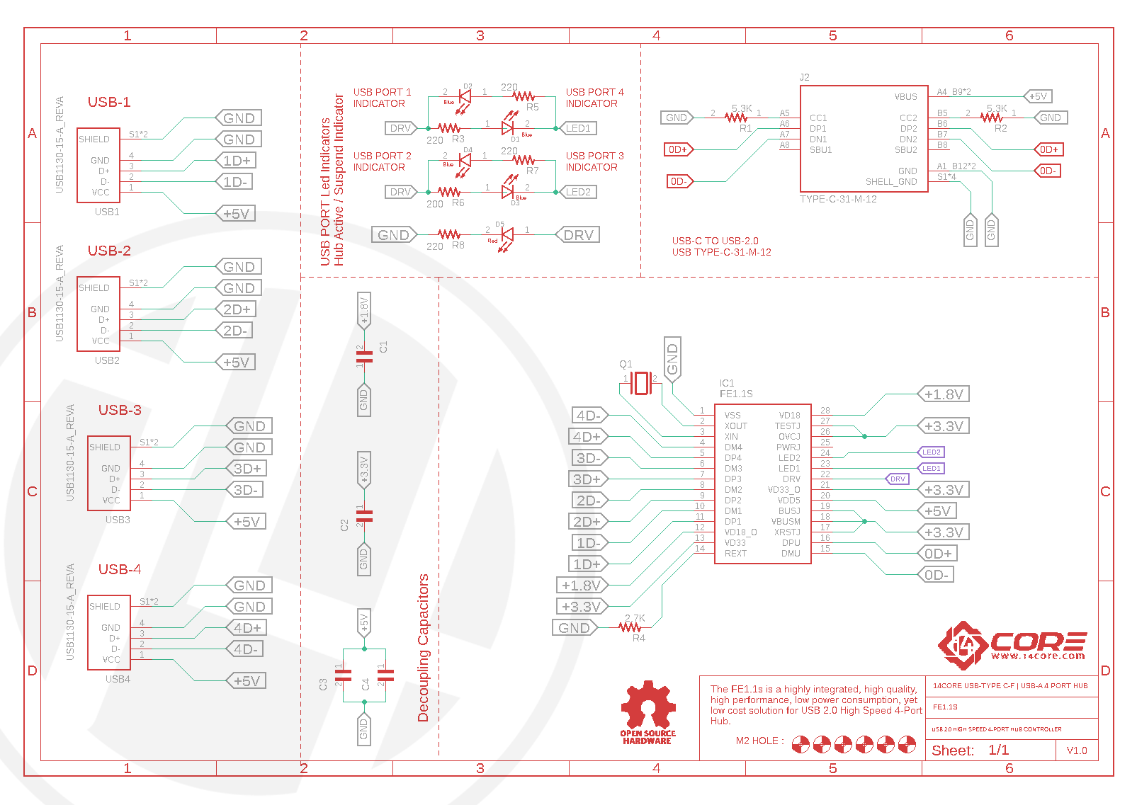
The FE1.1S itself, which serves as the USB hub controller chip, requires a crystal oscillator and two capacitors that provide the clock signal for the chip, and the regulator and two capacitors which is to provide power to the chip.
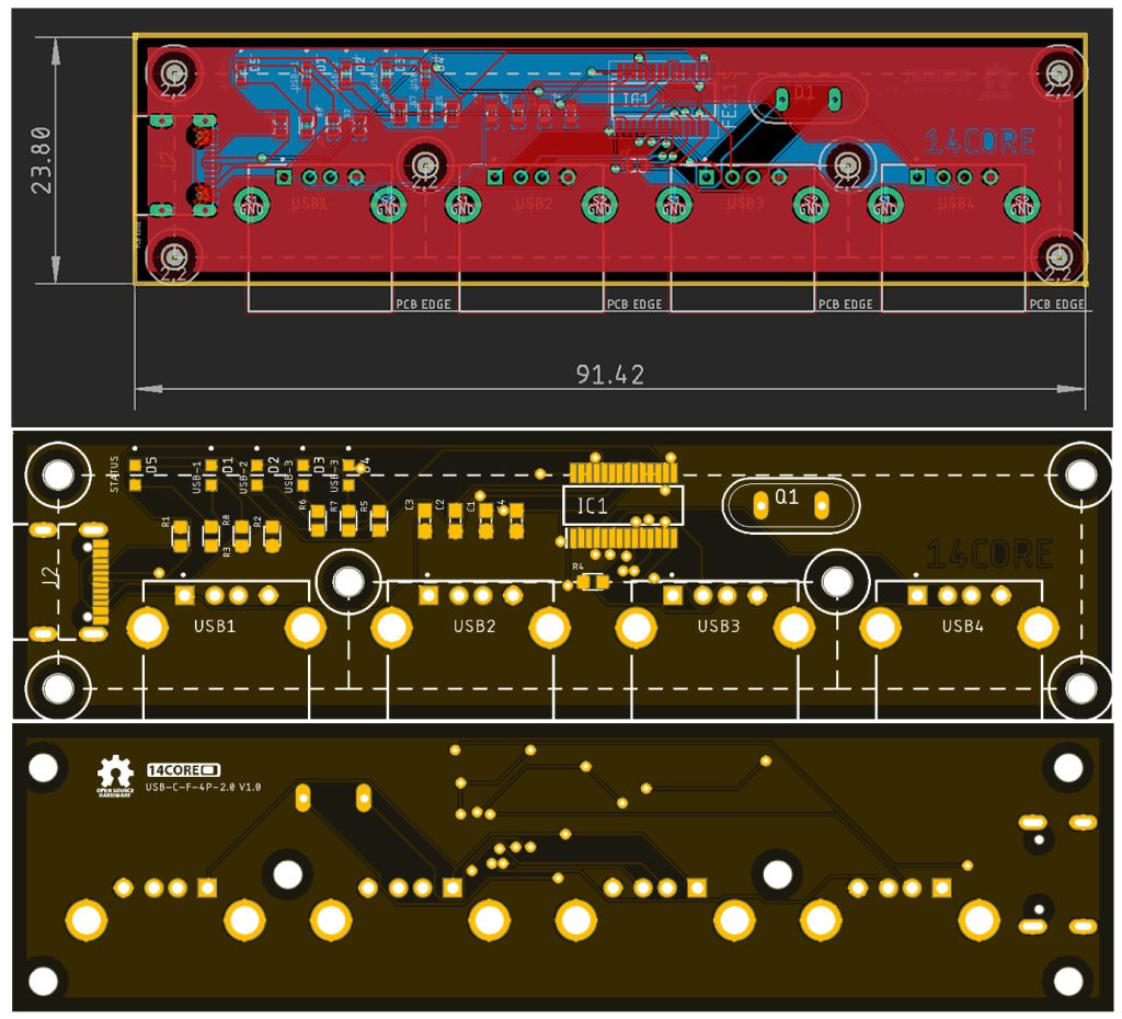

Gerber / Milling Files :
- Download PCB Milling File | 14CORE TYPE-C to USB-A HUB
- Download Gerber Viewer | Windows | Linux

