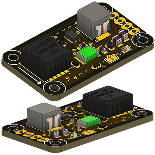
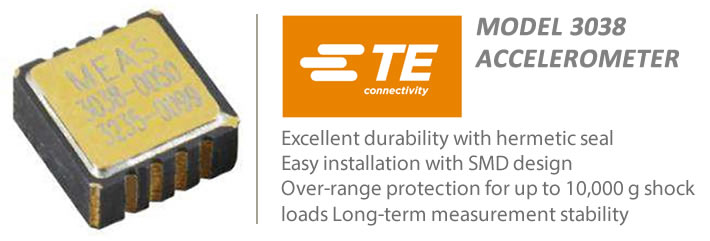
This is the TE 3038, TE 3038 is a type of MEMS (Micro-Electro-Mechanical System) accelerometer that is designed to measure acceleration and tilt. It uses a microelectromechanical system (MEMS) to detect changes in acceleration and converts this into an electrical signal that can be measured and analyzed. The TE 3038 MEMS accelerometer is a 3-axis accelerometer, which means it can measure acceleration in three dimensions: X, Y, and Z.
The TE 3038 MEMS accelerometer is a through-hole package with five pins. It can be connected to a microcontroller or other system to measure acceleration and tilt in various applications, such as Ammunition, Robotics, Drones, Vibration Detections, Shock Monitoring, Impack test, Automotive Applications, Intrumentations, Embedded Applications, Biomechanics Applications, Safe Arming, etc. The output from each axis is an analog voltage that is proportional to the acceleration in that axis, which can be read by an ADC (analog-to-digital converter) in a microcontroller or other system. The sensitivity value for this device is 330 mV/g, which means that for every 1g of acceleration, the output voltage will change by 330 mV.
Some List of Applications:
- Automotive: Can be used in automotive applications to detect motion or impact, such as airbag deployment, rollover detection, or stability control.
- Consumer electronics: Commonly used in smartphones, tablets, and gaming devices for features such as screen orientation, motion sensing, and gesture recognition.
- Aerospace: Used in aerospace applications to measure acceleration, vibration, and tilt in aircraft, spacecraft, satellites, and other vehicles. They can also be used in space exploration missions to provide feedback on the movement and orientation of spacecraft.
- Industrial: Can be used in industrial applications to monitor machinery vibration and detect equipment failure.
- Robotics: Used in robotics applications to detect motion and orientation of robotic arms, grippers, and other components.
- Industrial: In industrial applications, Can be used to detect machinery vibration and predict equipment failure. This can help to improve maintenance schedules, reduce downtime, and prevent costly repairs.
- Medical: Used in medical devices for monitoring patient activity and movement, such as in wearable health trackers or monitoring devices for patients with Parkinson’s disease.
- Sports: Can be used in sports applications to track the movements and performance of athletes. For example, they can be used in wearable devices to measure steps taken, calories burned, or distance traveled during physical activity.
- Navigation: Used in navigation systems, such as GPS, to measure the acceleration and movement of vehicles or devices. They can also be used in inertial navigation systems to provide precise location data even when GPS signals are unavailable.
- Smart homes: Can be used in smart home devices to detect motion, such as in security cameras or lighting systems that turn on automatically when someone enters a room.
- Virtual and augmented reality: Used in virtual and augmented reality devices to track the user’s movements and provide a more immersive experience.
- Energy harvesting: Can also be used in energy harvesting systems, where they are used to convert mechanical energy into electrical energy. This technology can be used to power small sensors or other low-power electronic devices.
- Structural health monitoring: Used in structural health monitoring systems to detect and diagnose damage or deterioration in buildings, bridges, and other infrastructure.
- Seismic monitoring: Can be used in seismic monitoring systems to detect earthquakes and other ground motion. They can also be used to measure the vibrations of buildings and other structures in response to seismic events.
- Environmental monitoring: Can be used in environmental monitoring systems to detect and measure changes in the natural environment, such as in the movement of glaciers or the behavior of ocean currents.
- Health monitoring: Can be used in wearable health monitoring devices to track and analyze a person’s movements, such as in fitness trackers or devices for monitoring sleep quality.
- Robotics: In addition to the applications mentioned earlier, Can be used in robotic prosthetics to provide feedback on the movement and orientation of the prosthetic limb.
- Industrial automation: Can be used in industrial automation applications to monitor the movement of machines and equipment, detect faults or malfunctions, and optimize performance.
- Military and defense: Used in military and defense applications to detect and measure the movement of vehicles, weapons, and other equipment. They can also be used in navigation systems for autonomous vehicles and drones.
- Structural testing and analysis: Can be used in structural testing and analysis to measure the response of structures to dynamic loads, such as in earthquake engineering or wind engineering.
- Vibration analysis: Can be used in vibration analysis applications to measure and analyze vibrations in machinery, such as in predictive maintenance systems for industrial equipment.
- Geotechnical monitoring: Can be used in geotechnical monitoring to measure ground motion and soil behavior, such as in earthquake engineering or landslide detection systems.
- Oil and gas industry: Can be used in the oil and gas industry to detect and measure the movement of oil and gas pipelines, as well as to monitor the behavior of drilling equipment and other machinery.
- Wearable technology: Used in a wide range of wearable technology, such as smartwatches and fitness trackers, to measure movement and activity levels, track steps and distance, and monitor sleep quality.
- Human-computer interaction: Can be used in human-computer interaction systems, such as gesture recognition or virtual reality interfaces, to track and respond to movement and orientation.
- Agriculture: Can be used in agricultural applications to measure the movement of crops, detect and prevent soil erosion, and monitor the behavior of farm equipment.
- Smart city infrastructure: Can be used in smart city infrastructure, such as traffic monitoring systems and pedestrian detection systems, to measure movement and provide data for traffic management and urban planning.
Overall, the broad range of applications for MEMS accelerometers demonstrates their versatility and usefulness in a wide variety of industries and fields. As technology continues to evolve, it is likely that new and innovative applications for MEMS accelerometers will continue to emerge, making them an essential component of many different types of sensors and monitoring systems.
The TE 3038 MEMS accelerometer is a small, low-cost sensor that measures acceleration in three dimensions. It is based on MEMS (Micro-Electro-Mechanical Systems) technology and has a range of +/- 3g. The sensor has a built-in 3-axis accelerometer and provides analog output signals in the form of voltage proportional to acceleration in each of the three dimensions (X, Y, and Z).
Technical information:
This sensor has a supply voltage of 5V DC. The datasheet for this device specifies that the voltage input range should be between 4.75V and 5.25V DC. It’s important to ensure that the input voltage stays within this range to avoid damage to the sensor or inaccurate readings. for more technical details please refer to the datasheet below.
- Range: +/- 3g
- Sensitivity: 330 mV/g
- Bandwidth: 1600 Hz
- Supply voltage: 5V DC
- Operating temperature range: -40°C to +85°C
- Dimensions: 14.0 x 12.0 x 4.0 mm
Requirements & Parts List:
| Part | Value | Device | Package |
| C1,C2 | 4.7uF | Capacitor | 0805 |
| C3, C6 | 0.1uF | Capacitor | 0603 |
| C4 | 47pF | Capacitor | ‘0603 |
| C5 | 22uF | Capacitor | ‘0603 |
| D1 | SMD | SMD Led | 1608 |
| F2 | ASMD1812-200-FUSE | Fuze | FUSC4632X130N |
| IC1 | AP63357DV-7-REG-DC | Regulator | AP63357DV7 |
| L1 | 6.8uH | Inductor | IND_ETQP4M6R8YFN |
| R1 | 93.1K | Resistor | ‘0603 |
| R2 | 22K | Resistor | ‘0603 |
| R3 | 41.2K | Resistor | ‘0603 |
| R4 | 220K | Resistor | ‘0603 |
| R5 | 330 | Resistor | ‘0603 |
| R6 | 0 Ohms | Resistor | ‘0603 |
| SV1 | Header Pin | MA04-1 | |
| U1 | 20005836-00 | TE 3038 Sensor | XDCR_20005836-00 |
Schematics Diagram:
Test Source Code :
Using a microcontroller with 14CORE TE 3038 sensor, you will need to connect the analog outputs of the sensor to the analog inputs of the MCU. The sensor provides three analog output signals in the form of voltage proportional to acceleration in each of the three dimensions (X, Y, and Z).
Here are the steps to connect the accelerometer to a microcontroller:
- Connect the VCC pin of the vibration & shock sensor to a DC power source with a range of 6 to 32v.
- Then connect the GND pin of the sensor to the ground of the microcontroller.
- Connect the X, Y, and Z analog output pins of the accelerometer to the analog input pins of the MCU. However, You can use any available analog input pins on the microcontroller, but it’s recommended to use pins with built-in ADCs (Analog-to-Digital Converters).
- Depending on the microcontroller and the programming language you are using, you will need to write a code to read the analog input values from the shock & vibration sensor and convert them to meaningful acceleration values. This can be done by using a simple voltage divider circuit or an analog-to-digital converter (ADC) that is built into the microcontroller.
Once the sensor is properly connected and the microcontroller is programmed to read the analog input signals, you can use the accelerometer to detect motion, measure acceleration, and perform other tasks based on the application. Keep in mind that the accuracy of the accelerometer readings will depend on the quality of the power supply, the analog-to-digital conversion, and the processing algorithms used by the microcontroller.
Arduino Code:
[crayon-6917803364078674339281/]
Python Code:
[crayon-6917803364083280844602/]
STM32F103C8 w/d 16X2 LCD Display:
[crayon-6917803364088783141379/]
Gerber / Milling Files :
- Download PCB Milling File | 14CORE 3038 Vibration & Shock Sensor
- Download Gerber Viewer | Windows | Linux


