Another project that illustrates how to build a lighting system for Electronic Scooters and Bikes. However, this project also can be applied in car lightning accessories such as under chassis lightning or grill light effects using addressable LED Stripe & Microcontroller. See below the required components.

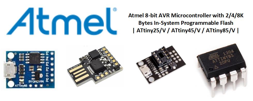
The 8Bit ATTINY AVRT Microcontroller
ATtiny25/45/85 is a low-power CMOS 8-bit microcontroller based on the AVR enhanced RISC architecture. By executing excellent instructions in a single clock cycle, the ATtiny25/45/85 achieves throughputs resembling 1 MIPS per MHz allowing you to optimize power consumption versus processing speed.
Requirements and Alternatives
- Arduino IDE | PlatformIO | Visual Studio Code
- ATTINY85 Chip or Modules
- SONY SPRESENSE Development Board
- Please refer to this link
- ESPRESSIF Microcontrollers
- 3S 20Amp Battery Management System / Battery Protection Board)
- N-Channel MOSFET
- 12v Addressable LED Strip WS2812
- 4x or 6x Li-Ion 18650 Battery 3.7v-2500mAH
- Tactile Switch
- Push Button
- Resistors (See below-required values)
- Capacitor(See below-required values)
- Others (see below diagram for other requirements)
Wiring Diagram
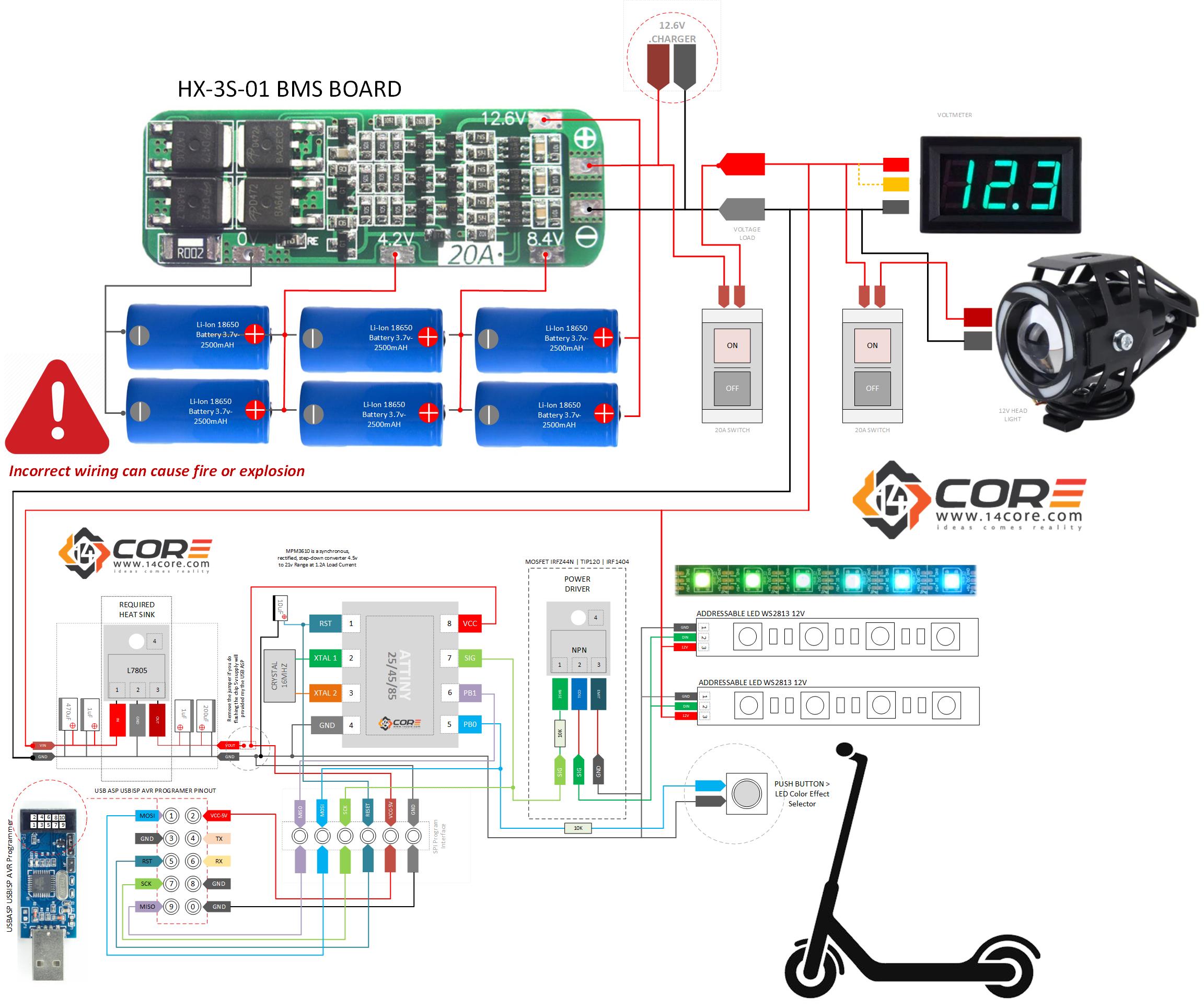
Wiring Diagram Schematics for 3S 12v 20A BMS / BPB
The 3S 20A 12.6v Lithium BMS (Battery Management System / Battery Protection Board) comes with an auto-recovery function, with a nominal voltage of 3.6v, 3.7v Li-ion battery continuously discharges at 20A. keep in mind that the higher the load the board will become much hotter, in this case, need to mind the current load is in use. please refer to this link how to calculate load to the battery
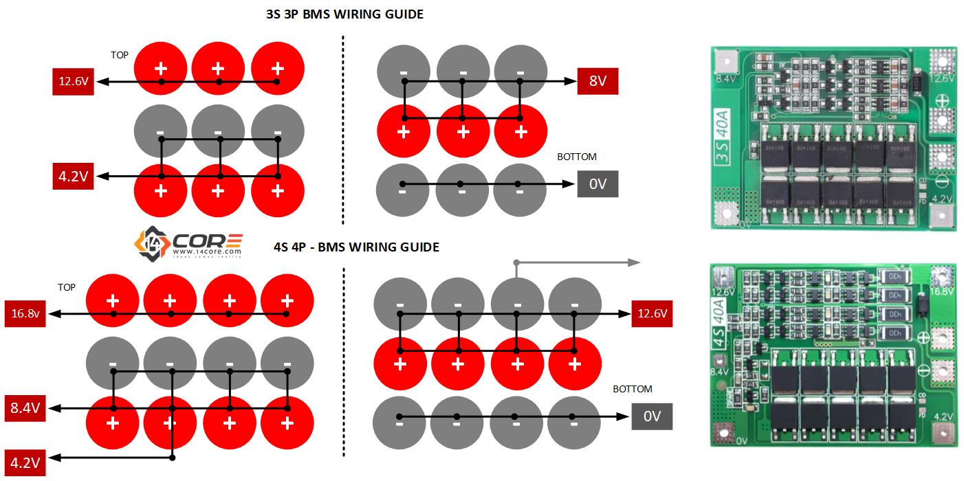
Wiring Digram for 3S 3P & 4S 4P 12v and 16v on BMS (Battery Management System)
Bootloading ATTINY85
As you can see in the diagram below it is segregated into 2 different ways to flash an ATTINY MCU. The first guide is using an Arduino MCU board as a chip programmer, and the 2nd guide is using a USBASP USBISP AVR Programmer. Keep in mind that when you program the chip you need to disconnect it from the 5v L7805 regulator.
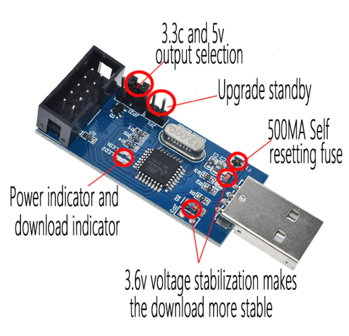
Steps how to bootload the ATTINY using USBASP AVR
Copy & Phase this the board manager > http://drazzy.com/package_drazzy.com_index.json
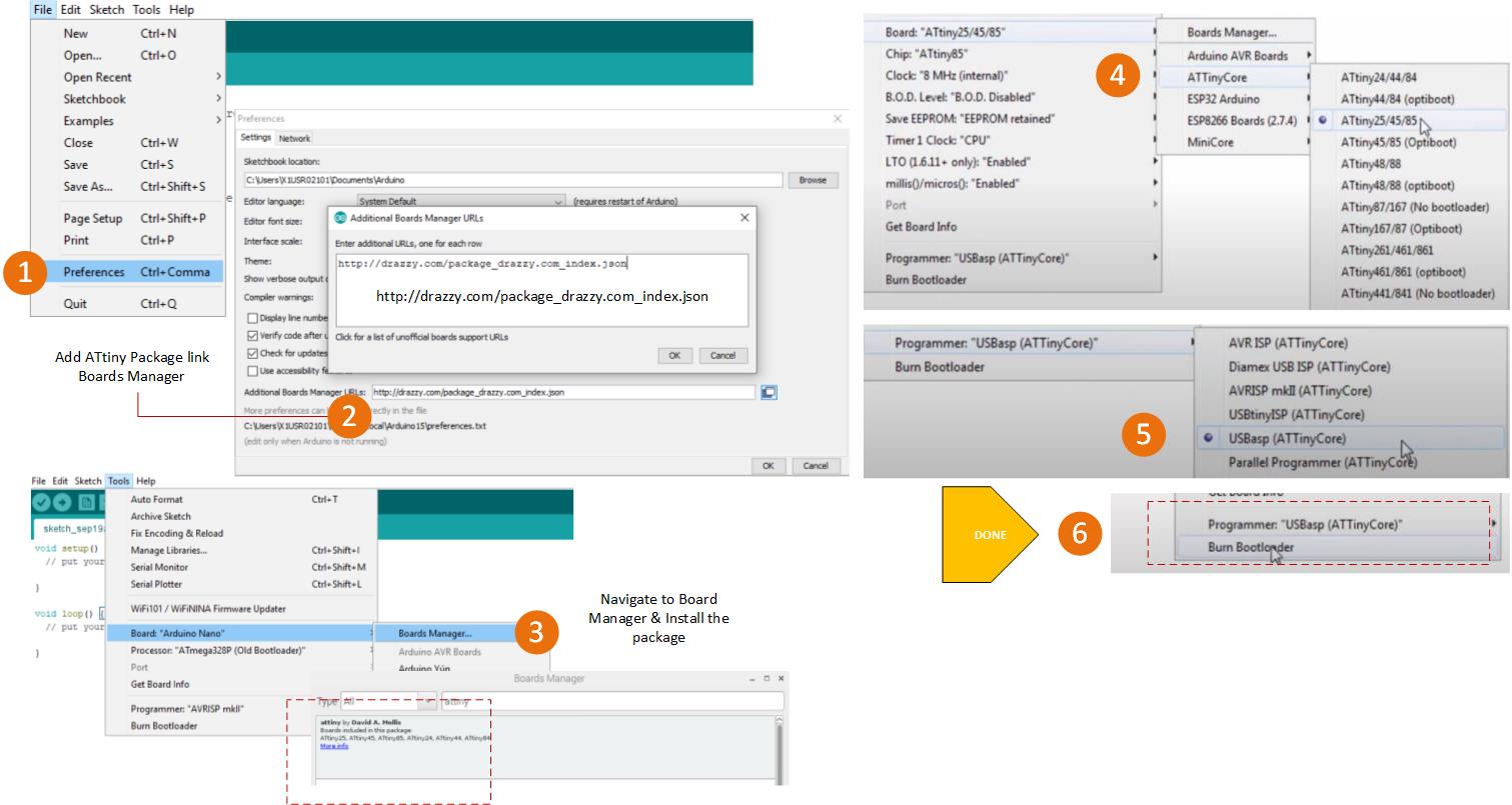
Any of these parts will be programmed by the use of any ISP (USB-UART) programmer. If using a version of Arduino before 1.8.13, be sure to choose a programmer with ATTinyCore after its name and connect the pins as normal for that ISP programmer.
Steps how to Bootload ATTINY85 using Arduino Board
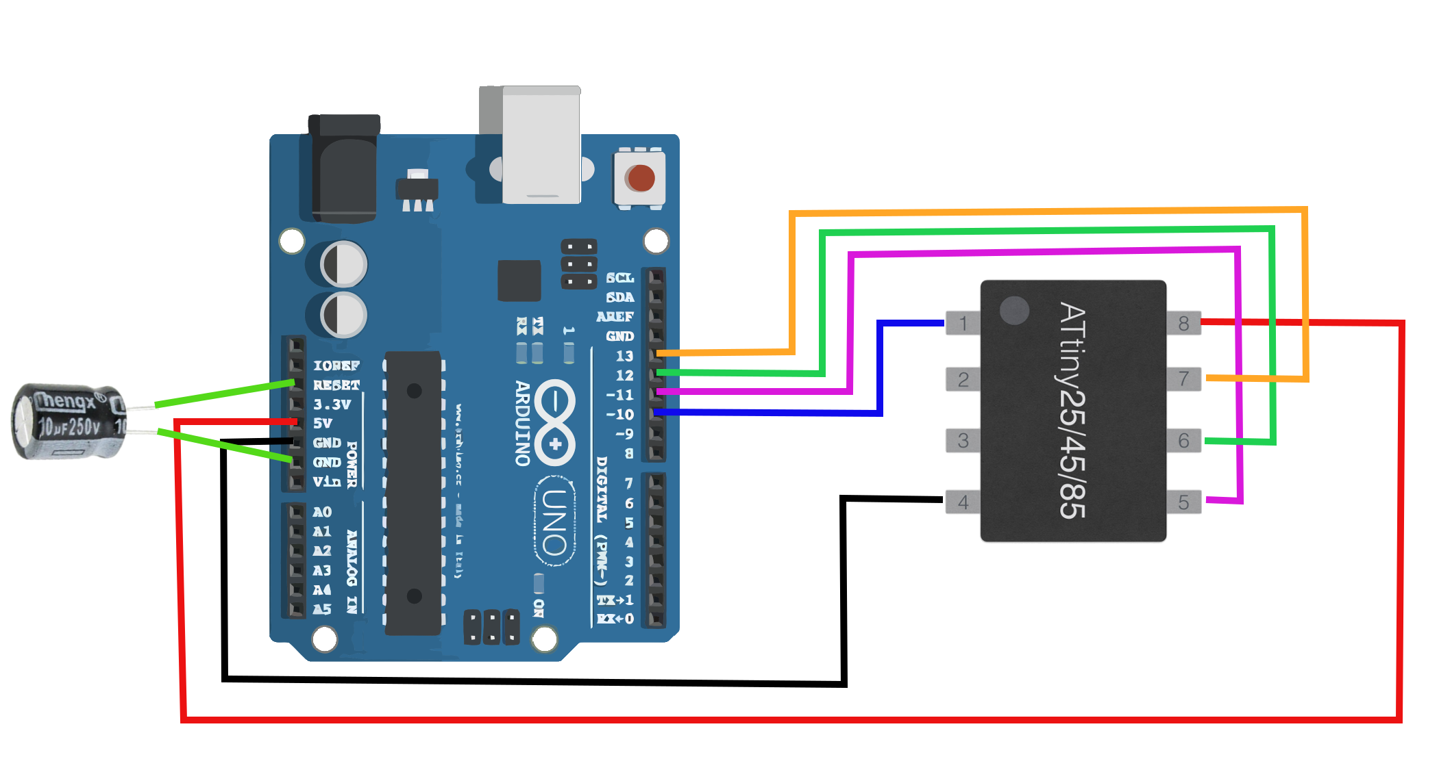
Copy this link & phase > https://raw.githubusercontent.com/damellis/attiny/ide-1.6.x-boards-manager/package_damellis_attiny_index.json > for wiring diagram how to hookup the ATTINY85 manually to Arduino board please refer to this link.
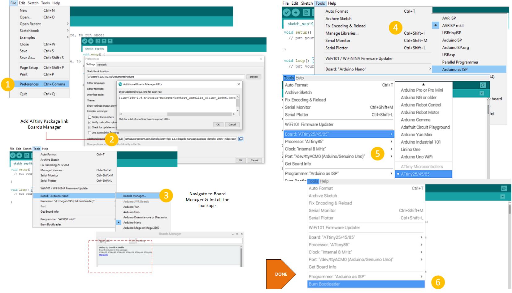
To program our ATtiny Microcontroller with Arduino Bootloader we need to first set Arduino Uno as an ISP. Attach the Arduino Uno to the PC. Open the Arduino IDE and open the ArduinoISP example file (File -> Examples -> ArduinoISP) and upload it. If there are no error messages your Arduino should be good to go. A wiring diagram can be found here, how to hook the ATTINY MCU to the Arduino board. | Copy this link & phase > https://raw.githubusercontent.com/damellis/attiny/ide-1.6.x-boards-manager/package_damellis_attiny_index.json
Finally, we have now an 8MHz Arduino board with input/output pins. The ATtiny85 can run on 2.7-5.5V without a regulator – so a 3.7V LiPo can power the board and make a cheap, effective, slim Arduino board. The best way to verify that the ATtiny Arduino is working properly is to upload a simple code sketch. You can use the code below to run a LED light effects. If you can upload the sketch to the ATtiny85 then you have a fully working Arduino 8MHz ATtiny85 Microcontroller, the possibilities are nearly identical to the ATmega328p, except for fewer ports and some limitations. However, the ATtiny Arduino is fully capable of managing analog read and writing, digital reading and writing, UART communication, power-down modes, SPI-interface, interrupt capabilities. However, you can now load the code below directly to ATTINY85 with your IDE.
Source Code
Downloads
- ATTIY Core Bootload Source
- Project Source Code with Library Zip
- LED Effects Library | WS2812 Library Zip
- Download FastLed Library Including Examples Zip
- Download ATTINY85 Datasheets PDF
- Download L7805 Datasheet PDF


