


ATmega32U4 and ATmega16U4 are both MCU from Atmel Corporation (now a part of Microchip Technology), which are based on the AVR architecture. They are similar in many ways, but there are some distinctions between the two.
The ATmega32U4 is an 8-bit microcontroller with 32 KB of flash memory and 2.5 KB of SRAM. It has 26 I/O pins, 12 of which can be used as PWM (Pulse with Modulation) outputs, and it also integrated USB controller, making it ideal for use in applications that require USB connectivity. The ATmega32U4 can operate at a maximum frequency of 16 MHz and has a wide range of operating voltages (2.7V to 5.5V).
On the other hand, the ATmega16U4 is also an 8-bit MCU, but it has 16 KB of flash memory and 1 KB of SRAM. It has 22 I/O pins, 4 of which can be used as PWM outputs, and it also includes a USB controller. The ATmega16U4 can operate at a maximum frequency of 16 MHz and has a similar range of operating voltages (2.7V to 5.5V).
In terms of features, both MCU’s have a range of built-in peripherals, including timers, USARTs, SPI, and I2C interfaces, as well as analog-to-digital converters and digital-to-analog converters. They also both support in-system programming and debugging, making them easy to work with.
The main difference between the two MCU’s is the amount of flash memory and SRAM they have, as well as the number of I/O pins and PWM outputs. If your application requires USB connectivity, then the ATmega32U4 may be the better choice due to its additional I/O pins, larger memory, and a greater number of PWM outputs. However, if your application does not require USB connectivity and has simpler I/O requirements, then the ATmega16U4 may be a more cost-effective option. However this is depends on your budget and projects costing including requirements.
- Architecture: AVR 8-bit RISC
- Operating Voltage: 2.7V to 5.5V
- Flash Memory: 32KB
- SRAM: 2.5KB
- EEPROM: 1KB
- Clock Speed: Up to 16 MHz
- I/O Pins: 26 (some of which can be used for PWM)
- USB 2.0 Full Speed Controller
- Analog-to-Digital Converter (ADC): 10-bit resolution, 12 channels
- Digital-to-Analog Converter (DAC): 10-bit resolution
- Timers: Three 16-bit timers and one 8-bit timer
- USART: One Universal Synchronous/Asynchronous Receiver/Transmitter
- SPI: One Serial Peripheral Interface
- I2C: One Inter-Integrated Circuit interface
- Watchdog Timer (WDT)
- In-System Programming (ISP) and In-System Debugging (ISD)
Some of the key features of the ATmega32U4 microcontroller include its USB 2.0 Full Speed Controller, which allows for easy integration with USB devices and hosts, and its large amount of flash memory, SRAM, and I/O pins. The microcontroller also includes a range of built-in peripherals, such as ADCs, DACs, timers, USART, SPI, and I2C interfaces, making it a versatile choice for a wide range of applications. The microcontroller also supports in-system programming and debugging, which can simplify the development process and reduce time-to-market.
when selecting a microcontroller, it is important to consider factors such as the required processing power, memory requirements, number of I/O pins, available peripherals, and cost. Choosing the right microcontroller can help you optimize your design and reduce the cost and complexity of your project.
ATmega32U4 is a universal MCU that can be used in a wide range of projects, thanks to its large amount of flash memory, SRAM, and I/O pins, as well as its built-in USB controller. Here are some project ideas that can make use of this microcontroller:
Here is the list of projects where the ATMEGA32U4 can be used:
- USB Devices: The built-in USB controller makes the ATmega32U4 ideal for making a USB devices, such as keyboards, mice, game controllers, or USB-to-serial converters.
- HID Projects: The HID (Human Interface Device) protocol is supported by this devices, which makes it a great choice for projects that require interfacing with a computer or mobile device as a human interface device. For example, you can use it to create custom input devices like game controllers, MIDI controllers, or custom keypads.
- Robotics and Automation: ATmega32U4’s wide range of I/O pins, timers, and communication interfaces make it suitable for use in robotics and automation projects. For example, you can use it to control motors, sensors, and other peripheral devices in a robotic or automation system.
- Smart Home Devices: ATmega32U4 can also be used in smart home projects, such as home automation systems, smart lighting, or temperature control. Its built-in USB controller can also be used to connect to other smart devices in the home.
- Audio Projects: This ATmega32U4’s built-in DAC can be used for audio playback or recording. You can use it to create custom audio players or recorders, or to interface with other audio devices.
- Internet of Things (IoT) Devices: ATmega32U4 can be used to create IoT devices that can connect to the internet, such as smart home devices, environmental sensors, or wearable devices. It can be used with Wi-Fi or Ethernet modules to connect to the internet.
- Game Development: This ATmega32U4 can be used to create custom games or game controllers. You can use its I/O pins to connect buttons or joysticks, and its built-in USB controller to communicate with a computer or game console.
- Data Acquisition and Logging: The ATmega32U4’s built-in ADC can be used to collect data from sensors, such as temperature sensors, humidity sensors, or light sensors. The data can be logged to an SD card or transmitted to a computer via USB.
- Industrial Control: This ATmega32U4 can be used in industrial control applications, such as process control, motor control, or machine automation. Its I/O pins and communication interfaces can be used to interface with a wide range of sensors and actuators.
- Educational Projects: This ATmega32U4 is a great microcontroller for educational projects, such as teaching programming or electronics. Its built-in USB controller allows it to be easily connected to a computer, and its wide range of peripherals and communication interfaces make it suitable for a variety of projects.
- Medical Devices: The ATmega32U4 can be used to build medical devices, such as blood glucose meters, pulse oximeters, or electrocardiogram (ECG) monitors. Its built-in ADC can be used to collect biological data, and its USB interface can be used to transfer data to a computer for analysis.
- Security Systems: The ATmega32U4 can be used to build security systems, such as access control systems, alarm systems, or surveillance cameras. Its I/O pins can be used to interface with sensors, such as motion sensors or door sensors, and its communication interfaces can be used to send alerts to a remote monitoring station.
- Wearable Devices: The ATmega32U4 can be used to build wearable devices, such as fitness trackers, smart watches, or health monitors. Its built-in USB controller can be used to connect to a computer or mobile device, and its low power consumption makes it ideal for battery-powered devices.
- Audio Effects: The ATmega32U4’s built-in ADC and DAC can be used to create custom audio effects, such as guitar pedals or vocal processors. Its I/O pins can be used to interface with analog inputs, such as guitar pickups or microphones, and its USB interface can be used to transfer audio data to a computer or recording device.
- Automotive Applications: The ATmega32U4 can be used in automotive applications, such as car alarms, GPS trackers, or dashboard displays. Its I/O pins can be used to interface with sensors and actuators, such as temperature sensors or motor drivers, and its communication interfaces can be used to interface with other automotive systems.
- Robotics: The ATmega32U4 can be used to build robots, such as line-following robots or remote-controlled robots. Its built-in PWM channels can be used to control motors, and its communication interfaces can be used to send commands to the robot.
- Human-Machine Interfaces: The ATmega32U4 can be used to build human-machine interfaces, such as touch screens or virtual keyboards. Its built-in USB controller can be used to interface with a computer or mobile device, and its I/O pins can be used to interface with touch sensors or key switches.
- Lighting Control: The ATmega32U4 can be used to build lighting control systems, such as smart light switches or LED controllers. Its I/O pins can be used to control relays or LED drivers, and its communication interfaces can be used to interface with other lighting control systems, such as DMX512.
- Test and Measurement: The ATmega32U4 can be used to build test and measurement equipment, such as multimeters or oscilloscopes. Its built-in ADC can be used to measure voltage or current, and its USB interface can be used to transfer data to a computer for analysis.
- Music and Audio Synthesis: The ATmega32U4 can be used to build music and audio synthesis systems, such as MIDI controllers or synthesizers. Its built-in ADC and DAC can be used to interface with musical instruments or audio equipment, and its communication interfaces can be used to interface with other music equipment, such as synthesizers or sequencers.
- Home Automation: The ATmega32U4 can be used to build home automation systems, such as smart thermostats or door locks. Its I/O pins can be used to interface with sensors or actuators, such as temperature sensors or servo motors, and its communication interfaces can be used to interface with other home automation systems, such as Z-Wave or Zigbee.
- Data Loggers: The ATmega32U4 can be used to build data loggers, such as weather stations or GPS loggers. Its built-in ADC can be used to measure environmental data, and its USB interface can be used to transfer data to a computer for analysis.
- Smart Appliances: The ATmega32U4 can be used to build smart appliances, such as smart coffee makers or smart ovens. Its I/O pins can be used to interface with sensors or actuators, such as temperature sensors or relays, and its communication interfaces can be used to interface with other smart home systems, such as Amazon Alexa or Google Home.
- Industrial Control Systems: The ATmega32U4 can be used in industrial control systems, such as PLCs or motor control systems. Its built-in ADC and PWM channels can be used to interface with sensors and actuators, and its communication interfaces can be used to interface with other industrial control systems, such as Modbus or CAN bus.
- OBD-II Diagnostic Tool: The ATmega32U4 can be used to build an OBD-II diagnostic tool that can read and clear diagnostic trouble codes from a vehicle’s onboard computer. Its communication interfaces can be used to interface with the OBD-II port, and its USB interface can be used to transfer data to a computer for analysis.
- Instrument Cluster: The ATmega32U4 can be used to build an instrument cluster for a vehicle, displaying speed, RPM, fuel level, and other vehicle data. Its communication interfaces can be used to interface with sensors and the vehicle’s onboard computer, and its USB interface can be used for firmware updates.
- Infotainment System: The ATmega32U4 can be used to build an infotainment system for a vehicle, providing audio and video playback, navigation, and smartphone integration. Its communication interfaces can be used to interface with audio and video equipment, and its USB interface can be used for firmware updates and to interface with smartphones.
- Adaptive Cruise Control: The ATmega32U4 can be used to build an adaptive cruise control system that automatically adjusts the vehicle’s speed based on the distance to the vehicle in front of it. Its communication interfaces can be used to interface with sensors and actuators, such as radar sensors and throttle actuators.
- Tire Pressure Monitoring System: The ATmega32U4 can be used to build a tire pressure monitoring system that displays the tire pressure of each tire in real-time. Its communication interfaces can be used to interface with tire pressure sensors, and its USB interface can be used for firmware updates.
- Fuel Injection Systems: The ATmega32U4 can be used to control fuel injection systems in gasoline or diesel engines. Its built-in ADC can be used to measure various engine parameters, such as air flow or oxygen levels, and its PWM channels can be used to control the fuel injectors.
- Electric Vehicle Control Systems: The ATmega32U4 can be used to build control systems for electric vehicles, such as motor controllers or battery management systems. Its communication interfaces can be used to interface with sensors and actuators, and its ADC channels can be used to measure various parameters, such as battery voltage or motor temperature.
- Head-Up Displays: The ATmega32U4 can be used to build head-up displays (HUDs) that project vehicle information onto the windshield. Its communication interfaces can be used to interface with sensors and the vehicle’s onboard computer, and its USB interface can be used for firmware updates.
- Lighting Control Systems: The ATmega32U4 can be used to control lighting systems in vehicles, such as headlights or interior lights. Its PWM channels can be used to control the brightness of the lights, and its communication interfaces can be used to interface with switches or other control systems.
- Telematics Systems: The ATmega32U4 can be used to build telematics systems that provide vehicle diagnostics, remote monitoring, and other services. Its communication interfaces can be used to interface with cellular or satellite networks, and its USB interface can be used for firmware updates.
- Parking Assist Systems: The ATmega32U4 can be used to build parking assist systems that help drivers park their vehicles. Its communication interfaces can be used to interface with ultrasonic sensors or cameras, and its I/O pins can be used to control actuators, such as steering or braking systems.
- Hybrid/Electric Vehicle Charging Systems: The ATmega32U4 can be used to build charging systems for hybrid and electric vehicles. Its communication interfaces can be used to interface with charging stations, and its ADC channels can be used to measure battery voltage and current.
- Engine Control Modules: The ATmega32U4 can be used to build engine control modules (ECMs) that control the operation of gasoline or diesel engines. Its built-in ADC can be used to measure various engine parameters, such as coolant temperature or throttle position, and its PWM channels can be used to control fuel injectors or ignition coils.
- Data Acquisition Systems: The ATmega32U4 can be used to build data acquisition systems that measure and record various industrial parameters, such as temperature, pressure, or humidity. Its built-in ADC channels can be used to measure analog signals, and its communication interfaces can be used to transmit data to a computer or a network.
- Motor Control Systems: The ATmega32U4 can be used to build motor control systems for industrial machines, such as conveyor belts, pumps, or compressors. Its PWM channels can be used to control the speed and direction of the motors, and its communication interfaces can be used to interface with sensors and other control systems.
- Human-Machine Interfaces: The ATmega32U4 can be used to build human-machine interfaces (HMIs) for industrial machines, such as touch screens or keypads. Its USB interface can be used to interface with a computer or a network, and its I/O pins can be used to control LEDs or other visual indicators.
- Industrial Automation Systems: The ATmega32U4 can be used to build automation systems for industrial processes, such as assembly lines or manufacturing plants. Its communication interfaces can be used to interface with sensors and actuators, and its USB interface can be used for remote monitoring and control.
- Energy Management Systems: The ATmega32U4 can be used to build energy management systems that monitor and control energy usage in industrial facilities. Its communication interfaces can be used to interface with energy meters and sensors, and its ADC channels can be used to measure various energy parameters.
- Laboratory Instrumentation: The ATmega32U4 can be used to build laboratory instruments, such as spectrometers or chromatographs. Its communication interfaces can be used to interface with sensors and other devices, and its USB interface can be used to transmit data to a computer.
- Environmental Monitoring Systems: The ATmega32U4 can be used to build environmental monitoring systems that measure and record various environmental parameters, such as temperature, humidity, or air quality. Its communication interfaces can be used to transmit data to a computer or a network, and its ADC channels can be used to measure analog signals.
- Control Systems for Scientific Equipment: The ATmega32U4 can be used to build control systems for scientific equipment, such as telescopes or microscopes. Its communication interfaces can be used to interface with sensors and other control systems, and its I/O pins can be used to control motors or other actuators.
- Data Loggers: The ATmega32U4 can be used to build data loggers that record and store data from various scientific experiments or processes. Its USB interface can be used to transfer data to a computer or a network, and its ADC channels can be used to measure analog signals.
- Electronic Test Equipment: The ATmega32U4 can be used to build electronic test equipment, such as oscilloscopes or signal generators. Its PWM channels can be used to generate signals, and its communication interfaces can be used to interface with sensors and other devices.
- Patient monitoring systems: Can be used in devices that monitor a patient’s vital signs, such as heart rate, blood pressure, and oxygen saturation. The microcontroller can interface with various sensors to collect and process data, and communicate the results to a display or a remote system.
- Medical devices: Can be used in medical devices, such as insulin pumps, blood glucose meters, and nebulizers. The microcontroller can control the operation of the device, monitor the patient’s input or output, and provide feedback to the user.
- Laboratory equipment: Can be used in laboratory equipment, such as spectrophotometers, chromatographs, and centrifuges. The microcontroller can control the operation of the equipment, collect and process data, and communicate the results to a computer or a display.
- Assistive devices: Can be used in assistive devices, such as prosthetics, hearing aids, and visual aids. The microcontroller can interface with various sensors and actuators to control the device, monitor the user’s input or output, and provide feedback to the user.
Requirements & Part List
Arduino IDE | VisualStudio Code | PlatformIO | ATMEL / MICROCHIP Studio
| # | PARTS | VALUE | DEVICE | PACKAGE | QTY |
| 1 | 3.3V-REG | 3.3V Regulator | AP2112K-3.3TRG1 | SOT95 | 1 |
| 2 | C1,C2,C4,C5,C7,C9 | 0.1uF | 0603CAPS | 603 | 6 |
| 3 | C3,C6 | 1UF | 0603CAPS | 603 | 2 |
| 4 | C8, C10 | 22pF | 06035A220JAT2A | 603 | 2 |
| 5 | D1, D2 | LED | KPT-1608ZGC | 1608 | 2 |
| 6 | L1-1UH | Inductor | DFE201210S-1UH-0805 | 805 | 1 |
| 7 | PS1 | 5V Regulator | MCP1754ST-5002E_CB | SOT95 | 1 |
| 8 | R1, R2 | 22 Ohms | 0603RES | 603 | 2 |
| 9 | R3 | 1K | 0603RES | 603 | 1 |
| 10 | R4 | 10K | 0603RES | 603 | 1 |
| 11 | R5,R6 | 330 Ohms | R0603 | 603 | 2 |
| 12 | U1 | ATMEGA32U4-AU | ATMEGA32U4-AU | TQFP | 1 |
| 13 | Y1 | ECS-160-20-23A-EN-TR | ECS-160-20-23A-EN-TR | SMD-2 | 1 |
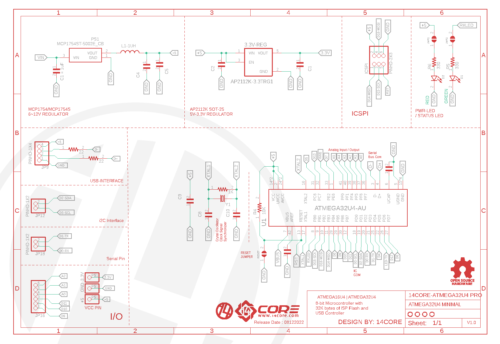
14CORE ATMEGA32U4 G2 Circuit Schematics:
Bootloading & Programming :
To program ATmega32U4 microcontroller using ATMEL STUDIO, which is a free integrated development environment (IDE) provided by the manufacturer. Here are the steps to program and bootload the ATmega32U4 using Atmel Studio:
- Connect your ATmega32U4 microcontroller to your computer using a USB cable with provided PIN which is mentioned at the schematics or using ICSPI.
- Open Atmel Studio and create a new project for your microcontroller.
- Select the appropriate programming device in the project settings, such as the Atmel AVRISP mkII or the Atmel AVR Dragon.
- Write your code using the Atmel Studio IDE, or import your code from another source.
- Compile your code to generate an executable file (HEX file).
- Use the programming device to flash the HEX file onto the microcontroller, either through the ICSP (In-Circuit Serial Programming) interface or through the USB interface using the bootloader.
- Once the code is flashed onto the microcontroller, you can disconnect the programming device and power the microcontroller using an external power source.
The ATmega32U4 also includes a built-in USB bootloader, which allows you to program the microcontroller through the USB interface without the need for an external programmer. However, to use the bootloader, you can use software such as the FLIP (Flexible In-system Programmer) or the Arduino IDE. The Arduino IDE is a popular choice for programming and bootloading the ATmega32U4, as it provides a simple and user-friendly interface. To use the Arduino IDE, you need to install the appropriate drivers and select the correct board and COM port in the IDE settings. You can then write your code using the Arduino programming language, compile it, and upload it to the microcontroller using the built-in bootloader.
- Download and install the Arduino IDE from the official website.
- Open the Arduino IDE and go to Tools > Board and select “Arduino Leonardo” or “Arduino Micro” (depending on your board).
- Go to Tools > Port and select the COM port that corresponds to your board.
- Go to File > Examples > Basics and open the “Blink” sketch.
- Make any necessary changes to the sketch and click the “Upload” button to upload the sketch to the board.
- If this is the first time you are uploading a sketch to the board, you may need to put the board into bootloader mode by double-clicking the reset button on the board. This will cause the board to restart and enter the bootloader.
- Once the sketch has been uploaded, the board will automatically reset and start running the sketch.
Note: If you encounter any issues with uploading the sketch, you may need to install the appropriate drivers for your board. You can find the drivers on the manufacturer’s website or on the Arduino website.
In addition to the built-in USB bootloader, the ATmega32U4 also supports in-system programming (ISP) through the ICSP header. You can use an external programmer, such as the AVRISP mkII or the USBtinyISP, to program the microcontroller using the ICSP header.
Test Source Code:
keyboard.h library is used to simulate keystrokes on a computer as if they were typed from a keyboard. It lets you to create a virtual keyboard using an Arduino Bootloaded ATMEGA32U4 that can be used to control a computer or any other device that accepts keyboard input.
[crayon-67ebd8fa5d27d775446623/]
The Keyboard.h library provides functions such as Keyboard.begin(), Keyboard.end(), and Keyboard.write() that enable you to initialize the keyboard, send keystrokes, and terminate the keyboard connection. You can also use functions such as Keyboard.press() and Keyboard.release() to simulate key presses and releases, and Keyboard.print() to send characters as if they were typed from a keyboard.
To use this library, you will need an Arduino bootloaded ATMEGA32U4 that supports the HID (Human Interface Device) protocol. You will also need to connect the board to the computer using a USB pin. Some common applications of the Keyboard.h library include automating tasks on a computer, creating custom keyboard shortcuts, and controlling devices that accept keyboard input, such as game consoles or smart TVs.

Gerber / Milling Files :
- Download PCB Milling File | 14CORE ATMEGA32U4 MINI G2
- Download Gerber Viewer | Windows | Linux

